
High Voltage Pulse Generator Electronic Circuit
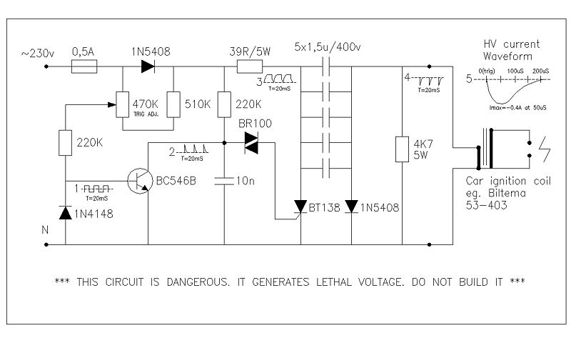
This circuit utilizes a high-voltage pulse generation mechanism, which is critical in applications requiring intense energy discharge. The primary component, a swing comparator circuit, operates by comparing input voltages and generating a controlled output that can drive a high-voltage transformer or coil. The design is based on a stroboscope trigger supply, which is known for its rapid pulsing capabilities, making it suitable for applications that demand precise timing and high energy.
The high-voltage output is capable of producing arcs up to 25 mm in length, indicative of the energy levels involved. The measurement of output current is performed by connecting a 10-ohm resistor in series with the output, allowing for the calculation of current through voltage drop observations using an oscilloscope. This method provides real-time feedback on the circuit's performance and allows for adjustments to be made to optimize the operation.
The control of the triggering event is achieved through a 470K potentiometer, which allows for fine-tuning of the phase angle between 180 and 270 degrees. This range is critical for ensuring that the output pulses are synchronized with the AC line frequency, thus maximizing the efficiency of the energy transfer.
Due to the high voltages and the nature of the circuit, safety precautions are paramount. The circuit should only be handled by individuals with appropriate expertise in high-voltage systems, and proper protective equipment should be used at all times. The circuit's design and operation highlight the importance of understanding the risks associated with high-voltage electronics, particularly in terms of potential electrical hazards and fire risks, as illustrated by the immediate ignition of paper placed near the arc.This circuit generates high voltage pulses from 230vac line voltage. The drive end`s swing comparator circuit is invented by the creator of this page. The work end is derived from stroboscope trig supply circuit. All line voltage using circuits are inherently dangerous, and this is particulary so. Do not build it. When powered up, the circuit gene rated fierce arc of 25mm length, between the coil secondary. The waveforms depicted in the schematic were observed. The output current was measured by letting the sparks ground via a 10ohm resistor, and measuring the voltage over the resistor with an oscilloscope. The trig event control was observed between ca. 180. 270 degrees of phase angle, by turning the 470K potentiometer. The sheet of paper placed between arc bursted immediately in flames. 🔗 External reference
Related Circuits
In this electronic roulette wheel, the 555 timer functions as a pulse generator with a fading frequency. The 4017 counter activates LEDs sequentially in the selected string, while a D-type flip-flop (4013 IC) serves as a divider by two...
This project is suitable for individuals who enjoy experimenting with electronics. It presents a low risk of damaging the unit. This project involves creating a simple electronic circuit that allows users to engage in hands-on experimentation without significant risk. The...
The TDA2040 is a monolithic integrated circuit housed in a Pentawatt package, designed for use as an audio class AB amplifier. It typically delivers an output power of 22W (with a distortion factor of 0.5%) at a supply voltage...
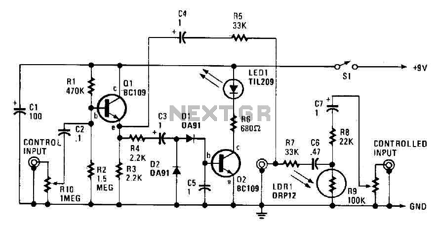
The automatic fader reduces the background music level when narration is in progress. The control input through RIO, a preset audio level control, is directed into an emitter-follower buffer stage (Q1). This buffer provides high input impedance and ensures...
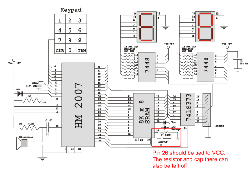
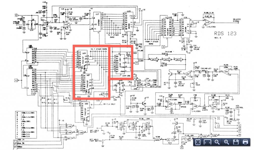
Verify the pin configurations on the datasheets for the integrated circuits used in your project, making necessary adjustments. In this instance, the RAM chip utilized had a non-inverted enable signal on pin 26, while the schematic assumed it was...
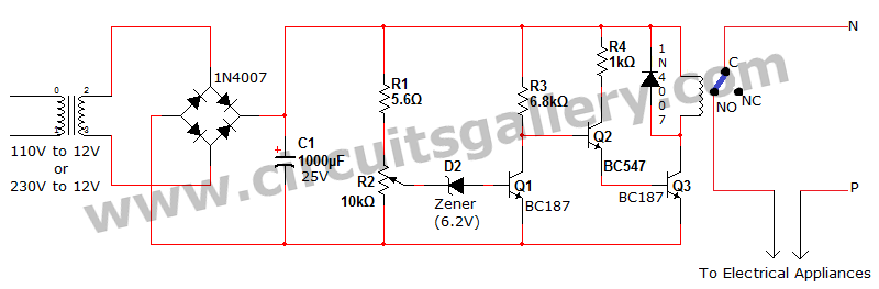
Voltage fluctuation is a significant concern in residential settings. For various reasons, the supply voltage may exceed 110V or 230V. This excessive voltage can potentially damage household electrical devices. An effective solution for electrical protection is the implementation of...
Warning: include(partials/cookie-banner.php): Failed to open stream: Permission denied in /var/www/html/nextgr/view-circuit.php on line 713
Warning: include(): Failed opening 'partials/cookie-banner.php' for inclusion (include_path='.:/usr/share/php') in /var/www/html/nextgr/view-circuit.php on line 713