
LED Modulation Circuits
The operation of LEDs necessitates precise control of the forward bias current to ensure optimal light output and longevity. The choice of semiconductor material directly influences the forward voltage and, consequently, the operating characteristics of the LED. The modulation circuits described utilize both discrete components and integrated circuits to achieve varying bandwidths and current modulation capabilities.
In the first modulation circuit, the transistor configuration is critical for maintaining a stable current source, which is essential for the consistent performance of the LED. The limitations imposed by the capacitance in the base-emitter junction highlight the importance of selecting appropriate component values to maximize the frequency response of the circuit.
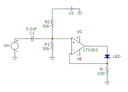
The second circuit's use of the LT1363 operational amplifier exemplifies modern design practices where high-speed components are leveraged to achieve greater modulation frequencies. The transconductance configuration allows for efficient conversion of voltage signals into current, which is particularly advantageous for driving LEDs in applications requiring rapid changes in light output.
Both circuits demonstrate the versatility of LED technology in various applications, from simple indicator lights to complex communication systems utilizing infrared signaling. Understanding the operational parameters and limitations of these circuits is essential for engineers designing LED-based systems.Common Light Emitting Diodes (LEDs) require a DC forward bias current of 10 to 20 mA for proper operation. Typically the maximum DC current is 30 to 50 mA. The color of light (or wavelength ») emitted from an LED depends on the semiconductor material used to fabricate the LED and this in turn determines the LED forward voltage at the operating cu
rrent. The forward voltage, which is roughly equal to the semiconductor bandgap potential of the active material in the LED is about 1 V for infrared LEDs with » ~ 880 - 920 nm such as those used in consumer remote-control devices, 1. 8 V for red LEDs at » ~ 660 nm, 2. 2 V for green LEDs at » ~ 560 nm and 3V for white LEDs. Infrared LEDs are available with analog modulation bandwidths of kHz to 20 MHz and higher. The circuits below demonstrate two basic approaches for analog current modulation of LEDs. The first circuit is useful for modulation up to about 5 MHz and uses a single transistor circuit biased as a firm current source with the LED in the collector circuit.
With the circuit components shown, the high frequency cutoff is about 4 - 5 MHz, limited by the base-emitter forward biased capacitance. The quiescent DC current through the LED as determined approximately by (Vcc/2 - 0. 7)/R5 or about 24 mA. The low frequency cutoff frequency is about 15 Hz. The output current modulation amplitude in midband is approximately Vs/R4. A 100 mV modulation input provides a current modulation of 10 mA. The second circuit is useful up to about 50 MHz and uses a high-frequency analog op amp, a Linear Technology LT1363 with a GBW of 70 MHz, a slew-rate of 1000 V/us and an output current drive capability of at least 50 mA: The circuit is a transconductance or voltage-to-current converter configuration.
The output is DC biased using a non-inverting input voltage divider network at a quiescent current of Vcc/2/Ri or about 15 mA using the component values shown with a supply voltage of +/- 10V. The modulation input is capacitatively coupled to the noninverting put via the RC lead network with a low-frequency modulation cutoff at about 3 Hz.
Since dynamic resistance of the LED is low compared to Ri the feedback fraction is roughly unity, and therefore the expected modulation bandwidth will be on the order of 70 MHz. To achieve a high LED current modulation index in this configuration, a large output voltage swing across Ri is required and for operation at high-frequency, a very high slew-rate op amp is needed.
For example, to achieve a peak modulation current of 10 mA (total is 25 mA) requires a modulation input of Vp ~ 3V. For modulation up to 50 MHz, the required slew-rate is 2*Pi*Vp*f or about 950 V/us which is just within the bandwidth and slew-rate specifications of the LT1363.
🔗 External reference
Related Circuits

A voltage-controlled oscillator using the NE555. This circuit is commonly referred to as a voltage-to-frequency converter because the output frequency is altered by varying the input voltage. As previously noted, pin 5 serves as the voltage control terminal, which...
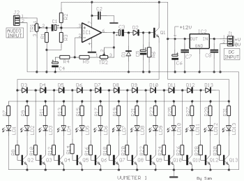
This circuit provides a simple visual indication of audio level signals, adaptable to various user requirements. It can be configured for different input levels, which can be adjusted using trimmer potentiometers TR1 (state) and TR2 (gain). The audio signals...
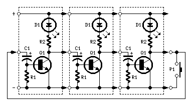
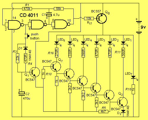
The purpose of this circuit is to create a ring in which LEDs or lamps illuminate sequentially. Its main feature is high versatility; it can accommodate any number of LEDs or lamps, as each illuminating device has its own...
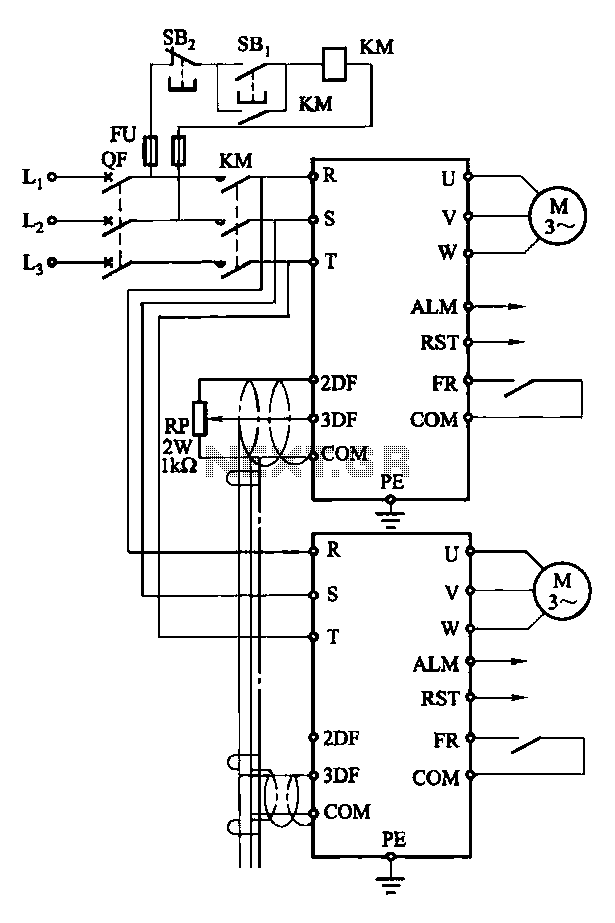
Each motor operates with an independent drive; however, only one frequency is utilized for a specific device. This setup employs a single RP potentiometer to control multiple motors in parallel. In this configuration, the circuit design allows for multiple motors to...
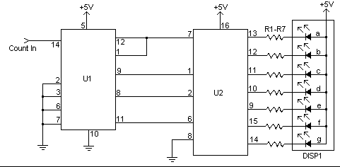
This simple counter can be utilized to count pulses, serving as the foundation for a customer counter, similar to those found at store entrances, or for any other counting applications. The circuit is compatible with any TTL logic signal...
The name of our game, LED Zeppelin, is a play on words. It comes not from the pop group of the same name but from Graf Von Zeppelin, a German who invented the first rigid air ship in 1900....