
LED RF Signal Strength Meter
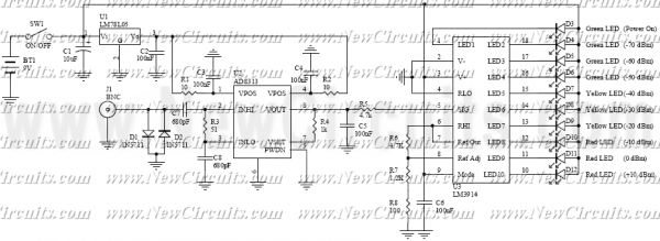
The RF Signal Strength Meter circuit is designed to measure the strength of radio frequency signals and provide a visual representation of the measured strength. The core component of this circuit is the AD8313 logarithmic detector, which is capable of accurately measuring RF signals across a wide dynamic range. The AD8313 operates by converting the logarithmic scale of the input RF signal into a corresponding DC voltage output, which is proportional to the signal strength. This allows for precise measurement and easy interpretation.
The output from the AD8313 feeds into the LM3914, a versatile LED display driver that can operate in either a dot mode or a bar mode. In this application, the LM3914 is configured to drive a series of 10 LEDs, each representing a specific range of signal strength in 10 dBm increments. The use of multiple LEDs provides a clear visual indication of the signal strength, making it easy for users to assess the quality of the RF signal at a glance.
The circuit may also include additional components such as resistors and capacitors to filter the signal and stabilize the operation of the AD8313 and LM3914. Power supply decoupling capacitors are typically used to ensure stable operation, while pull-down resistors may be employed to prevent floating inputs. The design can be further enhanced with a calibration feature, allowing users to adjust the LED indicators for accurate signal representation.
Overall, the RF Signal Strength Meter circuit is a practical tool for RF engineers and hobbyists alike, providing an effective means of measuring and visualizing RF signal strength in various applications. RF Signal Strength Meter circuits are popular RF measurement devices. This circuit is one of the simplest but very useful circuit that satisfies your desired accuracy. The heart of measurement is high accuracy but easy to use Logarithmic Detector AD8313 manufactured by Analog Devices company. To indicate the result, an LED train model indicator with 10dbm steps is used. As you can see in the schematic, 10 LEDs are drive by a Dot/Bar Display Driver LM3914 manufactured by National Semiconductor company. This type of indication enables you to us 🔗 External reference
Related Circuits
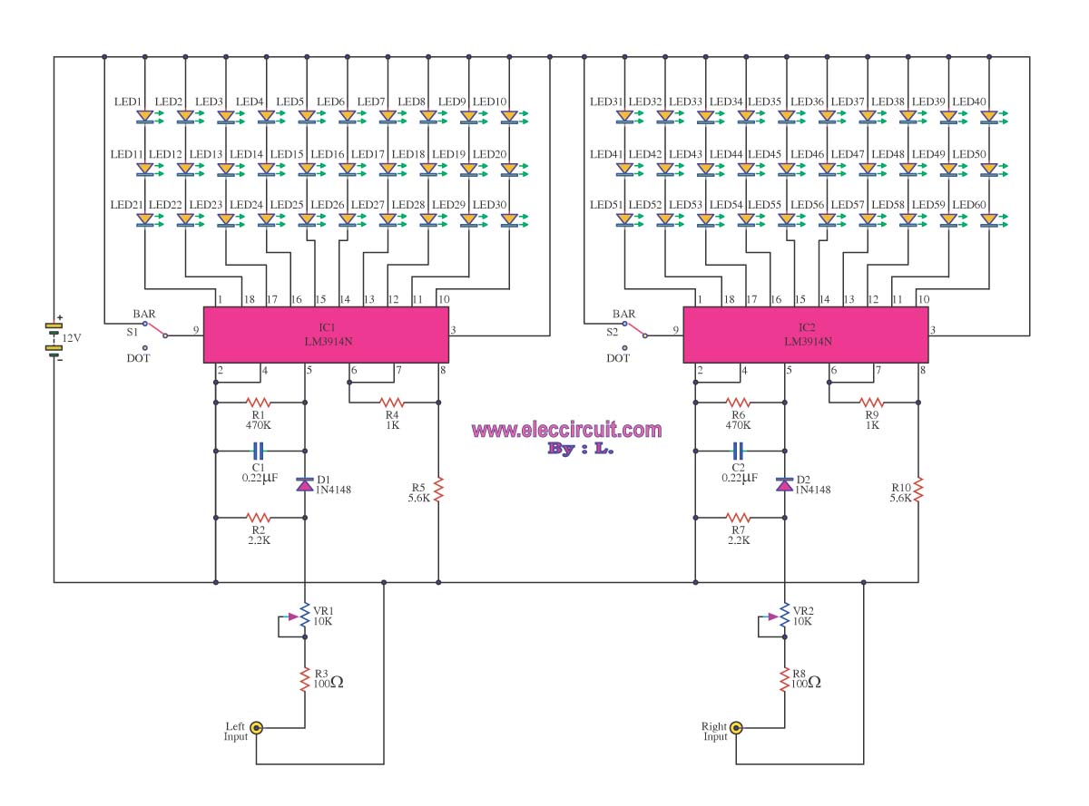
A VU meter is utilized to display the power level of audio signals and also serves as an aesthetic element. When purchasing a VU meter kit from an electronics store, options include assembling various parts independently or selecting a...
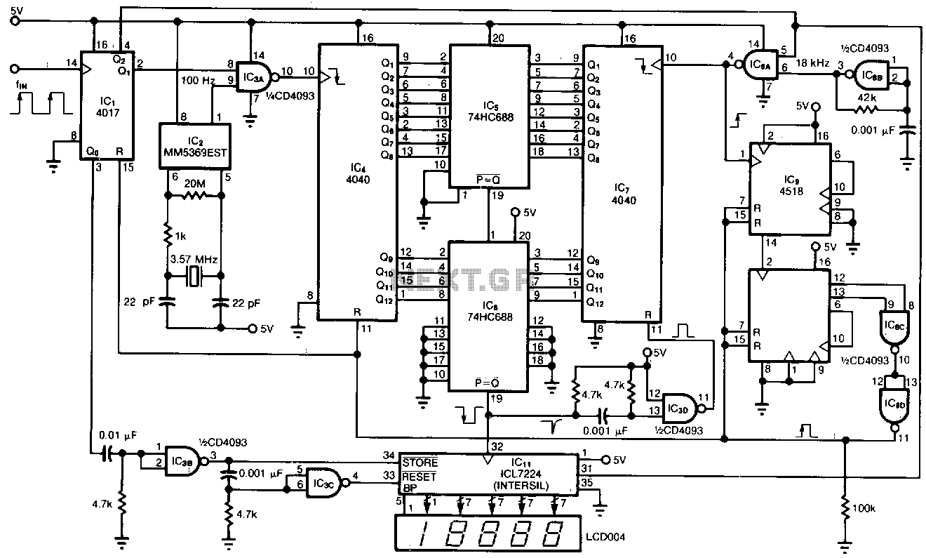
This tachometer allows for the measurement of heartbeats, respiratory rates, and other low-frequency events that occur at intervals ranging from 0.33 to 40.96 seconds. The circuit detects the frequency, calculates the corresponding pulses per minute, and updates the LCD...

In this circuit, A = 1, port = 0.5, and it features a passive vent filter without distinction. Attention is required when the circuit is dry; Q is determined by the formula Q = 1 / (3 - A)....

A10-V zener diode is utilized to extend the measurement range of a voltmeter from 0-5 V to a range of 10-15 V. An LED bar graph illuminates one segment for every 0.5 V increase above 10 V. Additionally, the...
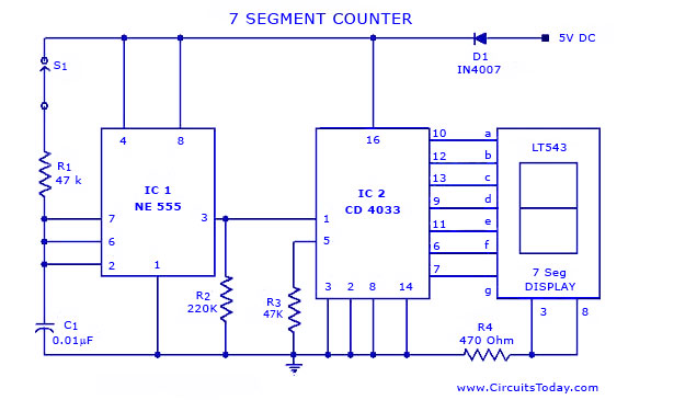
A simple seven-segment counter circuit with an LED display. This counter circuit diagram is designed using the IC CD 4033 as a counter, a 555 Timer IC, and a seven-segment LED display LT 543. The seven-segment counter circuit utilizes the...
This slideshow is based on the LED Design Ideas Collection, which features a compilation of LED-related circuits and design applications submitted by readers and published in EDN's Design Ideas section. Users can browse through the circuit schematics in this...