
Lets to build many VU Meter circuits with LM3914
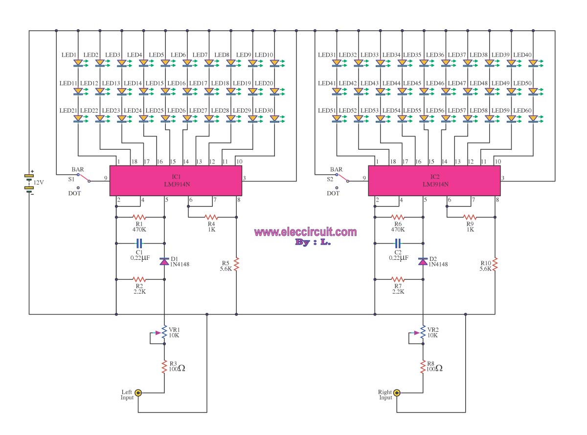
The VU meter circuit based on the LM3914 is designed to visually represent audio levels, making it an essential tool for audio engineers and hobbyists alike. The circuit's simplicity allows for easy assembly, while the use of the LM3914 IC ensures reliable performance across various audio applications. The ability to select between bar and dot displays enhances its versatility, catering to different user preferences. Furthermore, the inclusion of a transistor for low-level signal amplification expands its usability, enabling the monitoring of quieter audio sources without sacrificing accuracy. This circuit can be integrated into various audio equipment, such as mixers, amplifiers, and home audio systems, providing a visual cue for audio levels and preventing distortion due to excessive signal levels. Proper calibration of components, particularly R1 and R3, is crucial for optimal LED performance and longevity, ensuring that the VU meter operates within safe parameters while delivering accurate visual feedback. Overall, the LM3914-based VU meter circuit serves as an invaluable addition to any audio setup, combining functionality with aesthetic appeal.A VU Meter is used to display the power level of the audio, it also is beautiful. When you go to the electronic equipment store to buy the VU meter kit, with the assembly various parts on their own or the style ready to use. Most of us are using the IC-LM3914, because it is convenient, easy to modify in many form. Today I assemble a the circuits that use this IC. Sometimes you are looking for ideas on this. For example: Flashing lights by the band, to decorate the Christmas tree, exotic, and unique. VU meter circuit is an IC number LM3914. This is a circuit that is commonly used standards. Within the integrated circuit LM3914 is a voltage range advantage. This is the fourth leg split. Reference voltage pin 6 is low, and the reference voltage divided up. When raising the power supply circuit and the signal came, the sound signal to be via D1 Optical Direct Fire only split the signal to positive The C1 and R1 signal smoothing filter. Then, light is sent through R2 to access the input pin 5 of IC by the IC to the display of the signal starts from the output pin 1 or LED1 contiguous to the leg 10 or LED10.
You can choose form of a display 2. is a bar display and the display. Select use the switch S1. VR1 which acts on the set voltage reference ICs and R3 of the output current limiting function. If the value at which R3 LED1-LED10 are very bright. This is Circuit LM3914 LED VU Meter. use IC1-LM3914 and Transistor BC109C, By circuit will show level of audio signal(power Music) is dB in six level by LED display or also known as VU-METER. for the stereo system. In this : VU meter 10 LED using LM3914 is basic it can monitor 10 led but use for high signal, when we add the Q1-BC109 at input section to boost up current for low level signal input.
As you see, Be mono circuit but if you would to need stereo, you are going to make only other one. It is Build easily because use the integrated circuit just one and the price is inexpensive. The detail is all, see in the circuit better. This is a simple light running circuit by music This circuit is not difficult, is MONO, with a few accessories. Can be connected to the output of a CD or cassette player Time. Operation of the circuit. Begins to be input via VR. The VR will function fine, signal strength coming. D1 will take disconnected hemisphere plus leaving only the signal hemisphere removed to activation of Q1.
Signal is extended through Q1 to pin 5 input of IC1. By C1 forward delay of the IC is not the LED (connected to the output. of IC1) off immediately. The IC IC1 is finished. The act shows the effect of the voltage at IC1 pin 5 of the display by the LED to pins 1-19 of the IC, which is within range. compared to a multiple voltage standard circuits. The circuit can operate effectively. In the R1 that it will determine the current flowing through the LED. To prevent LED damage. Use should be connected to the input of the circuit. To the speaker terminals, change the value of R3 is 10k and IC1 can choose to display two types Bar (Bar) when the pin 9 and a power source.
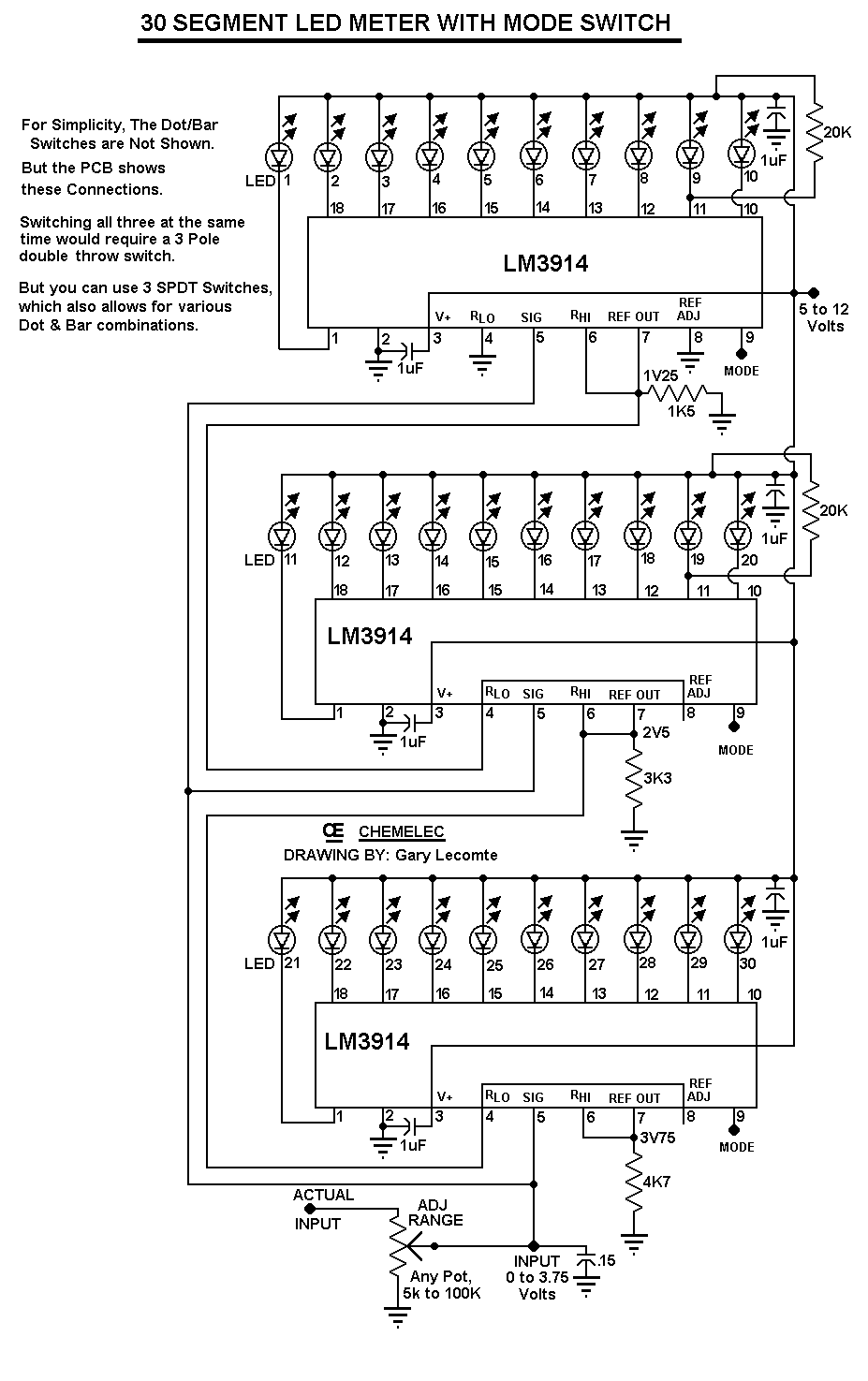
Dots (Dot) on 9-pin to float to drop. This circuit is another name for the VU meter. which often have a lot of equipment. Cause problems for people who start training. But this cycle is not much equipment. You can also choose, in the. Operation of the circuit. It is the primary device IC number LM3914N is ready to show the effects of pressure, as a bar or have a point. Behavior of IC1 and IC2 is similar circuit R2, R3, VR1 is connected in the manner divided voltage to the input to the voltage appropriate, through D1 to Pin 5.
by R1 and C1 are waiting delay. Input pin 5 not to fade away soon. When a signal to the output of each IC pin is connected to the 3-Series LED, to limit the flow. But if you want the L 🔗 External reference
Related Circuits
A new generation of intelligent, scriptable sensors/controllers is on the horizon. Traditionally, many simple machines utilized separate thermometer and control units. In contrast, this design presents a unified thermometric controller that can be programmed with simple scripts. It incorporates...
The 1K resistors in the circuit are essential for enabling the LEDs to activate at varying audio levels. This circuit is easily expandable with additional operational amplifiers and is not restricted to the use of the LM324. The 33K...
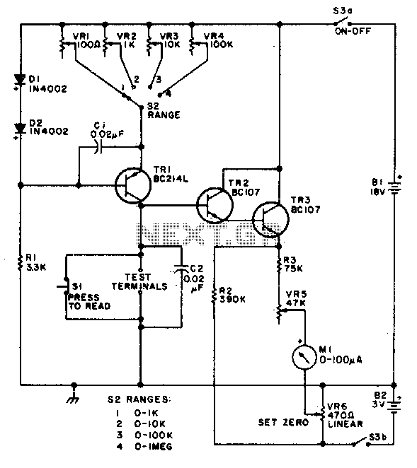
This circuit is designed to provide accurate measurement and a linear resistance scale at the high end. The circuit has four ranges. Additionally, another meter with a current range of 10 µA to 10 mA and a sensitivity of...
After the publication of the original Li'l 7 AM Transmitter plans, fellow experimenter Scott Todd shared information about his design for a similar portable, battery-powered transmitter. In his message, Scott mentioned that he noticed the absence of a battery-operated...
A vibration meter circuit depicted in the schematic diagram utilizes the LM3915 as the primary active component. This vibration meter employs a piezoelectric sensor. The vibration meter circuit is designed to measure and display vibration levels through a visual output....
The circuit can be easily configured for full-scale voltages of either 20 or 200 volts by utilizing a suitable potentiometer on the input. It is critical not to exceed 30 volts at pin 5 of the LM3914. A 20...
Warning: include(partials/cookie-banner.php): Failed to open stream: Permission denied in /var/www/html/nextgr/view-circuit.php on line 713
Warning: include(): Failed opening 'partials/cookie-banner.php' for inclusion (include_path='.:/usr/share/php') in /var/www/html/nextgr/view-circuit.php on line 713