
LED Sound level display circuit by using IC LM3915
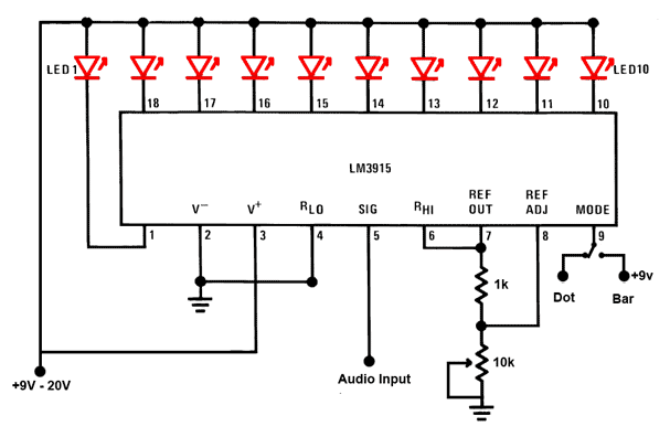
The audio sound level LED display circuit utilizes the LM3915 integrated circuit, which is designed for visualizing analog signals through a series of LEDs. This circuit is particularly useful for audio applications, where it provides a clear visual representation of sound levels. The LM3915 features a built-in logarithmic scale, allowing it to respond to sound levels in a manner that is perceptually relevant to human hearing, where sound intensity is typically perceived on a logarithmic scale.
The circuit is powered by a DC supply, with a recommended range of 9V to 12V for optimal performance. This voltage range ensures that the LEDs operate efficiently, providing adequate brightness while minimizing power consumption. The inclusion of a 10K ohm potentiometer allows for manual adjustment of the LED brightness, which can be particularly useful in different ambient light conditions or for different user preferences.
The audio input is connected to Pin-5 of the LM3915, which accepts a varying voltage signal corresponding to the audio level. This signal can be taken from various audio sources, including the output of an audio amplifier or other audio devices. The circuit's design supports versatility in application, making it suitable for home audio systems, musical instruments, or sound level monitoring in various environments.
Pin-9 serves a crucial function in the display mode selection, allowing users to choose between a dot mode, where a single LED indicates the current sound level, and a bar mode, where multiple LEDs light up to create a visual representation of the sound level. The ability to switch between these modes enhances the circuit's flexibility, catering to different display preferences or requirements for specific applications. Disconnecting Pin-9 from the positive voltage supply enables the dot mode, providing a dynamic visual cue that can be particularly engaging in live sound settings or performances.
Overall, this audio sound level LED display circuit is a straightforward yet effective solution for visualizing audio levels, leveraging the capabilities of the LM3915 integrated circuit to deliver a user-friendly and adaptable display system.This is a simple audio sound level LED display circuit diagram. The circuit is completely based on a single ic LM3915 from National Semiconductor. The LM3915 is a monolithic integrated circuit. It displays the audio sound level in terms of 10 LEDs and providing a logarithmic 3 dB/step analog display. The audio sound level LED display circuit can o perate from a single supply 3V to 25V. But I suggest to use 9-12V. LED brightness can be controlled with a single pot( variable resistor) as shown 10K ohm in the circuit. Connect the audio input signal in Pin-5 of LM3915 from output of a audio device like output of audio amplifier or any other source.
The Pin-9 of LM3915 is to select dot or bar mode display. To make the circuit moving dot display instead of a bar graph display disconnect the Pin-9 from +V. 🔗 External reference
Related Circuits
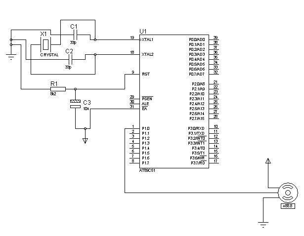
The control signals for the motor's rotation are generated by an 8051 microcontroller. For foundational concepts and information about a servo motor, refer to the article on Servo Motors. The source code utilized is based on the AT89S51 microcontroller....
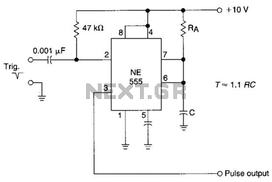
The time constant of RAXC determines the period of the monostable multivibrator. A negative pulse at pin 2 of the 555 starts the cycle. The monostable multivibrator is a circuit configuration that produces a single output pulse in response...
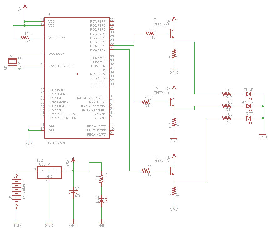
A very popular type of LED that has finally emerged is the tri-color, RGB LED. The RGB stands for red, green, and blue, as the LED is capable of displaying various colors through the combination of these three primary...
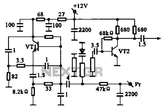
The local oscillator operates at frequencies of 1 GHz or higher, utilizing a common collector circuit, which makes it challenging to generate low-frequency self-oscillation. Typically, the local oscillator signal is passed through a buffer amplifier stage before being applied...
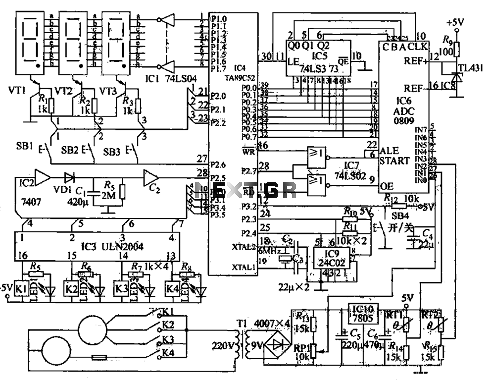
The circuit functions as a computer logo-conditioned temperature control system as depicted in Figure 1-58. The primary component is the AT89C52 microcontroller. When powered on, the 4C02 microcontroller first retrieves the last saved setpoint temperature and the operational state...
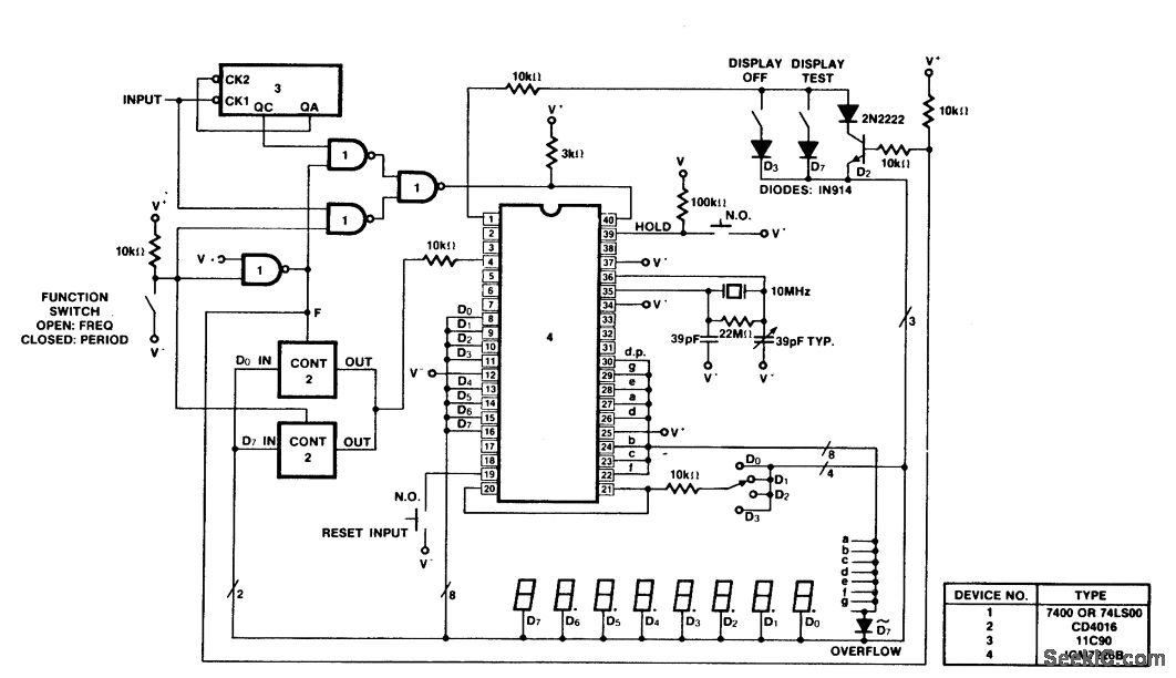
A 100 MHz frequency and period counter is constructed using the Intersil ICM7226B in a 40-pin DIP package. This circuit incorporates a CD4016 analog multiplexer to route the digital outputs back to the function input. The CD4016 operates as...