
Monostable Multivibrator Ii Circuit

The monostable multivibrator is a circuit configuration that produces a single output pulse in response to an input trigger. In this specific design, the time constant is primarily influenced by the resistor RAXC and the capacitor connected to it. The time constant, denoted as τ (tau), is calculated using the formula τ = RAXC × C, where RAXC represents the resistance in ohms and C denotes the capacitance in farads. This time constant dictates the duration of the output pulse generated by the multivibrator.
When a negative pulse is applied to pin 2 of the 555 timer integrated circuit, it triggers the monostable operation. The 555 timer is designed to recognize this negative transition as the start of a timing cycle. Upon receiving this trigger, the output at pin 3 goes high for a duration determined by the aforementioned time constant. After the elapsed time, the output returns to its low state, completing the cycle.
In practical applications, the selection of RAXC and the capacitor value is critical for achieving the desired pulse width. Adjusting these components allows for fine-tuning the timing characteristics of the circuit, making it suitable for various applications such as timers, pulse width modulation, and one-shot pulse generation. Proper design considerations must also include the power supply voltage, the load connected to the output, and the characteristics of the components used to ensure reliable operation of the monostable multivibrator. The time constant of RAXC determines the period of the monostable multivibrator. A negative pulse at pin 2 of the 555 starts the cycle.
Related Circuits
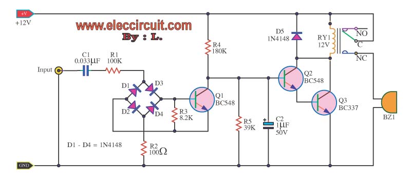
This circuit enables audio monitoring of a remote location, functioning as both a room monitor and a baby alarm. It can be powered by a 12-volt battery or a mains power supply. The interconnection utilizes three wires, allowing for...
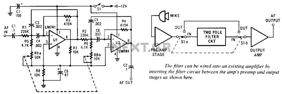
This variable-frequency audio bandpass filter is constructed using two 741 operational amplifiers (op amps) connected in cascade. Both op amps are configured as identical RC active filters, enhancing the selectivity of the overall circuit. The filter has a tuning...
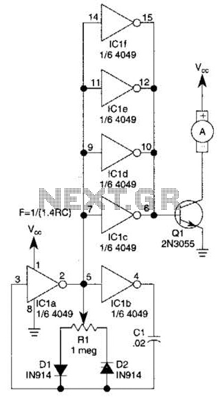
This circuit will drive a small DC motor over a wide range of speeds without stalling by controlling the duty cycle of the motor, rather than the supply voltage. The described circuit utilizes pulse width modulation (PWM) to effectively control...
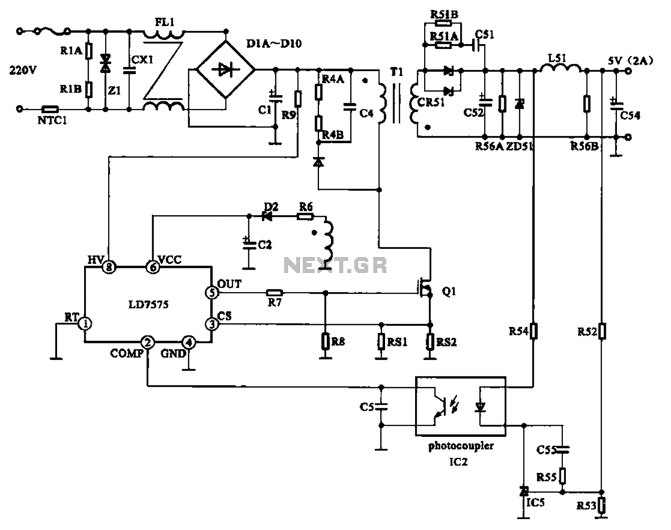
The AC adapter circuit is designed for portable digital products, converting low voltage DC into 220V AC. It features a circuit configuration for a switch power drill utilizing the oscillation IC LD7575 as a switch. This IC operates after...
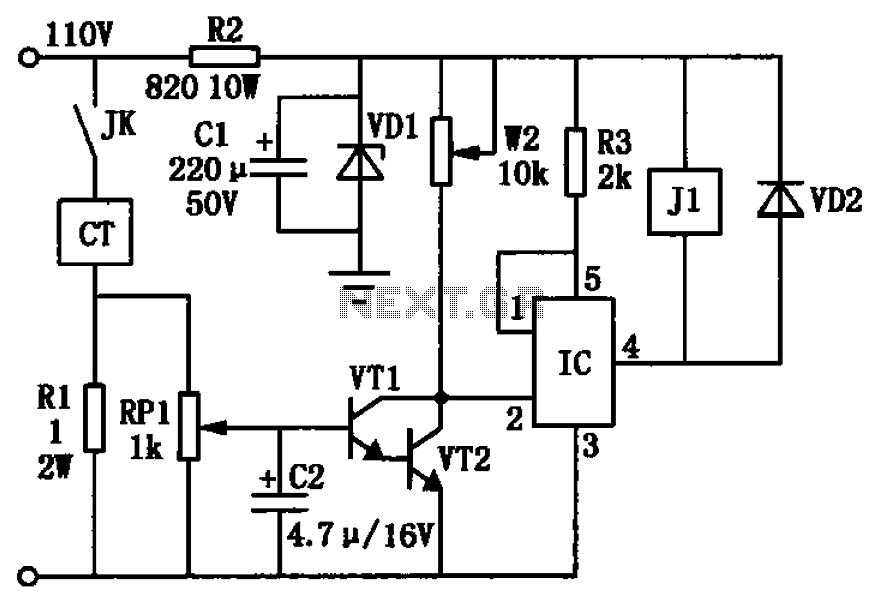
The circuit depicted in the figure utilizes a +24V power supply derived from a 110V power source through an electromagnetic chuck. When the electromagnetic chuck circuit is activated, the contact JK closes, enabling the operation of the magnetic chuck....
The telephone repeater is a circuit designed to amplify the call signal, making it louder than the original. This circuit has been developed in response to specific requests. The telephone repeater circuit functions by receiving the incoming audio signal from...