
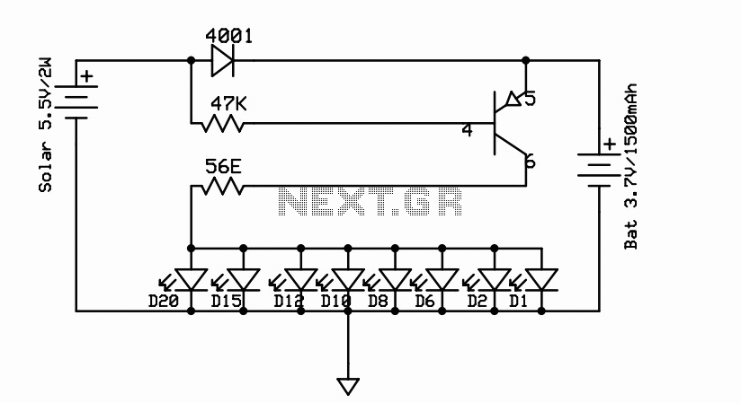
LED stepdown power supply

The described circuit functions as a proof of concept for a step-down (buck) converter designed primarily to drive a red LED with a forward voltage (Vf) of 1.9V using two nickel-cadmium (NiCd) batteries, allowing operation down to a voltage level of 2 volts. The circuit's design is notable for its efficiency, particularly in low-voltage applications, where the current sensing mechanism detects a minimal voltage drop of 18mV across a 1-ohm resistor. This low sensing voltage suggests that the circuit can monitor and regulate current effectively while maintaining high efficiency.
For applications requiring a white LED, which typically has a higher forward voltage than red LEDs, additional battery cells are necessary to meet the voltage requirements. Furthermore, the 1.0K ohm resistor, which is part of the feedback and control loop, must be increased to accommodate the higher current demands of the white LED.
The circuit employs a current mirror configuration, which is critical for maintaining stable operation and ensuring that the output current remains consistent despite variations in input voltage or load conditions. The inclusion of a 47K hysteresis resistor provides positive feedback from the driver transistor back into the current mirror, enhancing the circuit's stability and performance as a switching power supply. This feedback mechanism allows the circuit to switch efficiently between on and off states, thereby minimizing power loss.
To further enhance the efficiency of the step-down converter, several modifications can be considered. Utilizing a larger inductor can improve energy storage and transfer during the switching cycles, reducing ripple current and improving overall performance. Additionally, optimizing the switching speed of the transistor can minimize transition losses, contributing to better efficiency. Lastly, increasing the value of the 1.0K resistor can help manage output current more effectively, especially when driving higher-power LEDs.
It is important to note that the circuit can also be configured to operate in linear mode if the hysteresis resistor and inductor are removed. In this mode, the circuit would function differently, potentially providing a simpler linear regulation, but at the cost of efficiency, particularly in applications where the input voltage significantly exceeds the output voltage.Below is a proof of concept circuit which needs improvement. The part values shown will run a high efficiency red LED with a Vf of 1.9V from only 2 nicads, right down to 2 volts. For a white LED you will need more batteries and you must increase the 1.0K resistor to a higher value.
Current sensing at a mere 18mV over 1ohm makes this stepdown switcher efficient, but efficiency can be increased by using a larger inductor, improving transistor switching speed, or by increasing the value of the 1.0K resistor. Positive feedback from the driver transistor back into the current mirror through the 47K hysterisys resistor ensures that this circuit behaves as a switching power supply, however it could be used in linear mode if this resistor and the inductor were removed.
🔗 External reference
Related Circuits
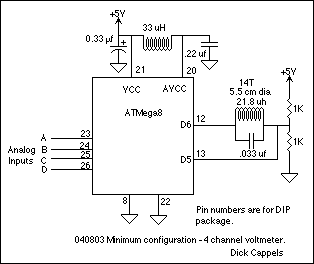
A 10 bit scanning voltmeter with a Minimum Mass Wireless Coupler, based on the ATMega8. Range to the Minimum Mass Base Unit is 10 to 15 cm. If the voltmeter is battery operated, it can be floated from ground....
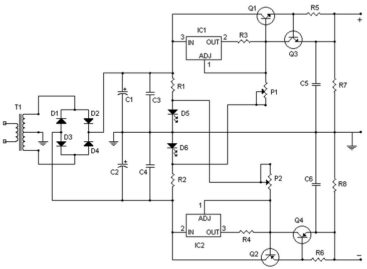
This circuit can deliver up to 15V per section (-15V and +15V), or up to 30V as a whole, for a maximum consumption of 2A. With modifications, it could be adjusted to provide up to 5A or more. Transistors...
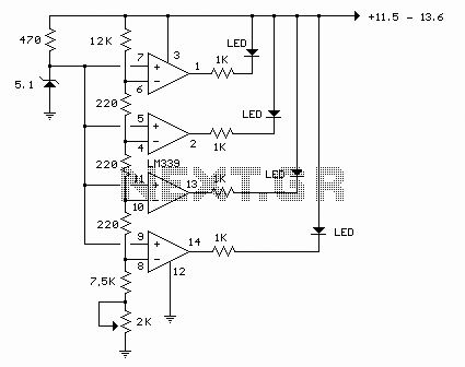
The circuit described utilizes a quad voltage comparator (LM339) to function as a simple bar graph meter that indicates the charge status of a 12-volt lead-acid battery. A 5-volt reference voltage is employed for this purpose. The circuit leverages the...
An efficient automatic solar garden lights circuit with minimal components. The advantage is that it operates entirely autonomously, with the solar panel functioning as a light detector. It switches the lamp off at dawn, charges the battery during the...
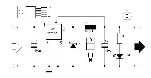
This circuit illustrates the LM2576T integrated circuit (IC) step-down switching power supply circuit diagram. Features include a 60V input voltage with output options of 3.3V, 5V, 12V, and 15V. The LM2576T is a popular voltage regulator known for its ability...
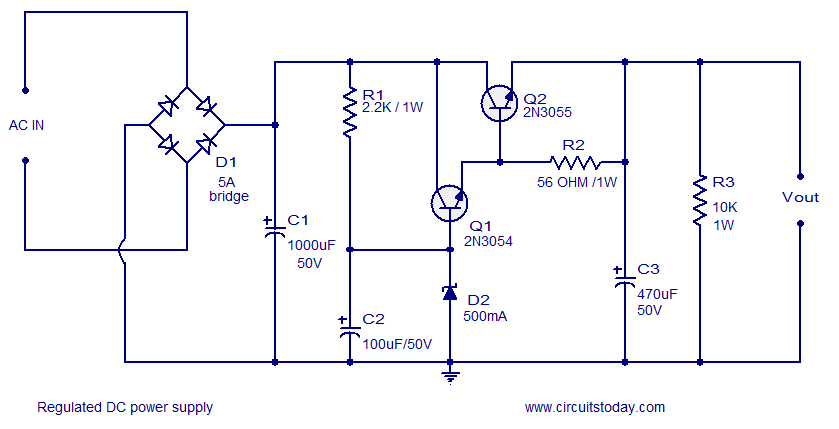
A low ripple regulated DC power supply designed using transistors is presented. These transistor voltage regulators are suitable for applications requiring high output current. Conventional integrated series regulators, such as the 7805, can only deliver up to 1A. To...