
LED tester circuit
Adjustment: Set a mA meter between A and K and adjust the power off with R1 for normal LEDs at 20mA. This current value is the normal stress according to the datasheet on the LED. This tester can also be used as a LED dimmer, but there is little or no difference between 15 and 30mA.
R1 = 100k trimming
R2 = 270Ω 1/4W
C1 = 100nF
C2 = 100nF
U1 = LM358N
U2 = 78L12
J1 and J2 = 2 print pins or pin headers
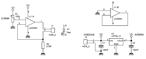
This LED tester circuit utilizes an LM358 operational amplifier (op-amp) configured as a power switch to control the current flowing through the LED under test. The circuit is designed to operate within a control range of approximately 0 to 30 mA, which accommodates a variety of standard LEDs. The power supply requirements are specified as a minimum of 15V, with the option of using a 12V adapter if the voltage regulator (U2, 78L12) is not operational.
The LM358 is a dual op-amp, but in this configuration, only one half is utilized for the current control function, while the other half is employed to facilitate a shutdown feature, enhancing the circuit's safety and usability. The circuit includes a jumper (J1) that connects pins 1 and 3 of the LM358, which is essential for the operation of the current control mechanism.
Capacitor C1, rated at 10 µF, is critical for stabilizing the power supply to the op-amp, ensuring reliable performance. Additionally, two 100 nF capacitors (C2) are included, likely for decoupling or filtering purposes, contributing to the overall stability of the circuit.
For calibration, a milliampere meter is connected between points A and K to monitor the current through the LED. Resistor R1, a 100 kΩ trimming potentiometer, allows for precise adjustment of the current, facilitating the setting of a nominal operating current of 20 mA, which is considered standard for many LEDs according to their datasheets. Resistor R2, specified as 270Ω with a 1/4W rating, is used in conjunction with R1 to define the current range.
The circuit also has the capability to function as a LED dimmer; however, it is noted that there may be minimal perceived difference in brightness between the current settings of 15 mA and 30 mA. The inclusion of pin headers (J1 and J2) facilitates easy connections and enhances the modularity of the circuit, allowing for straightforward integration into various testing setups.This ledtester uses as a power switched opamp. The control range is about 0-30mA. Thus, all test and standard LEDs, the voltage across the LED to read. The power supply is an example labvoeding at least 15V, 12V adapter if you're a U2 expires. Then put a jumper between pins 1 and 3 and use a 10uF electrolytic capacitor for C1. The LM358 is only half used the other half to the mass shut down. Adjustment: Set a mA meter between A and K and adjust the power off with R1 for normal LEDs is 20mA. This current value is the normal stress according datasheet on the LED may also be seen. This tester can also be used as leddimmer, but there is little or no difference between 15 and 30mA. R1 = 100k trimming R2 = 270? 1/4W C1 = 100nF C2 = 100nF U1 = LM358N U2 = 78L12 J1 and J2 = 2 print pins or pin headers 🔗 External reference
Related Circuits
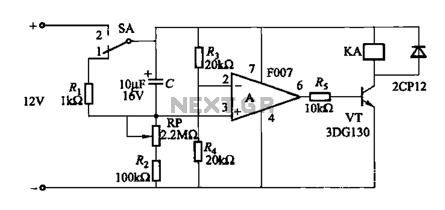
A delay circuit utilizing an operational amplifier functions as a comparator, providing high timing accuracy. The timer's delay range is from 1 to 30 seconds. The delay time is determined by resistors Ri, RP, and capacitor C. By adjusting...
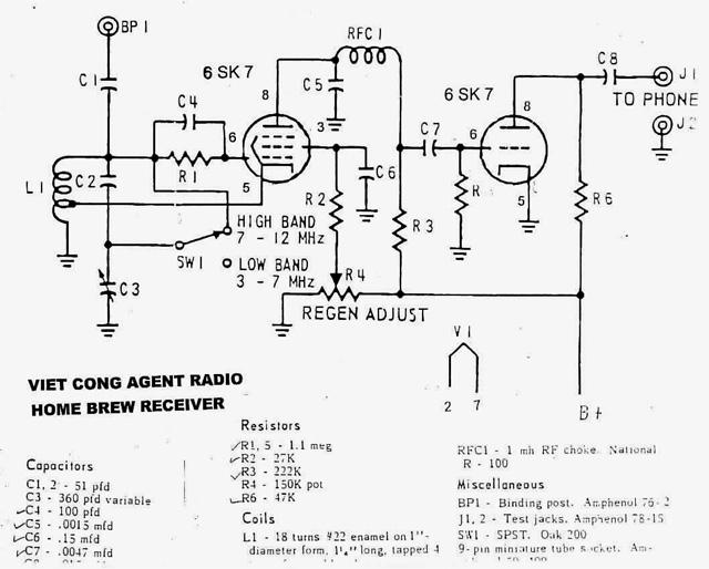
Army Radio Sales Co. specializes in military communications equipment for ham radio operators and collectors. The company offers a variety of military radios from various countries for sale and also engages in the buying and swapping of military radios...
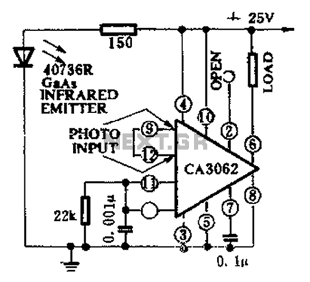
CA3062 is a combined photodetector and power amplifier that responds to the optical signal generated by the on/off output. The integrated circuit's transistor output saturation should be either on or off to prevent temperature rise in the silicon. When...

The automatic alarm circuit comprises a DTMF automatic dialing system, a password control circuit, a voice detection and alarm circuit, a telephone interface circuit, a power supply circuit, and a keyboard display circuit. The automatic dial-up alarm utilizes the...
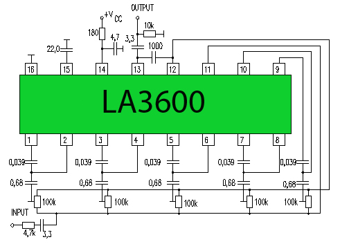
One type of tone regulator is the audio graphic equalizer, which can be categorized into two types: the audio graphic equalizer bar and the parametric equalizer. This article focuses on the bar type, specifically a 5-channel equalizer utilizing the...
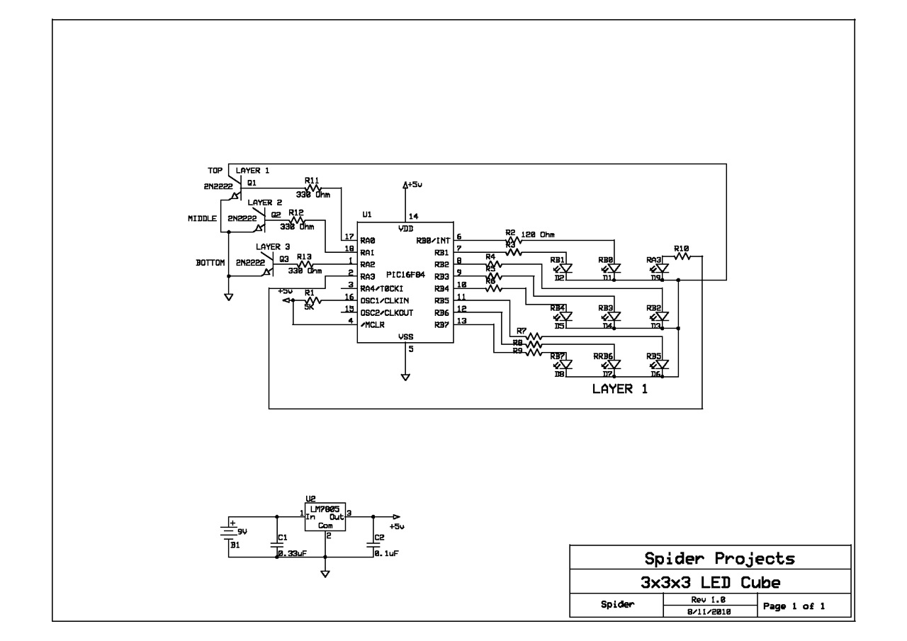
This schematic was sourced from the Internet and utilized for a prototype cube. The schematic only depicts the first LED layer, requiring the user to independently construct up to the third layer. A single current limiting resistor is employed...