
3x3 led cube schematic
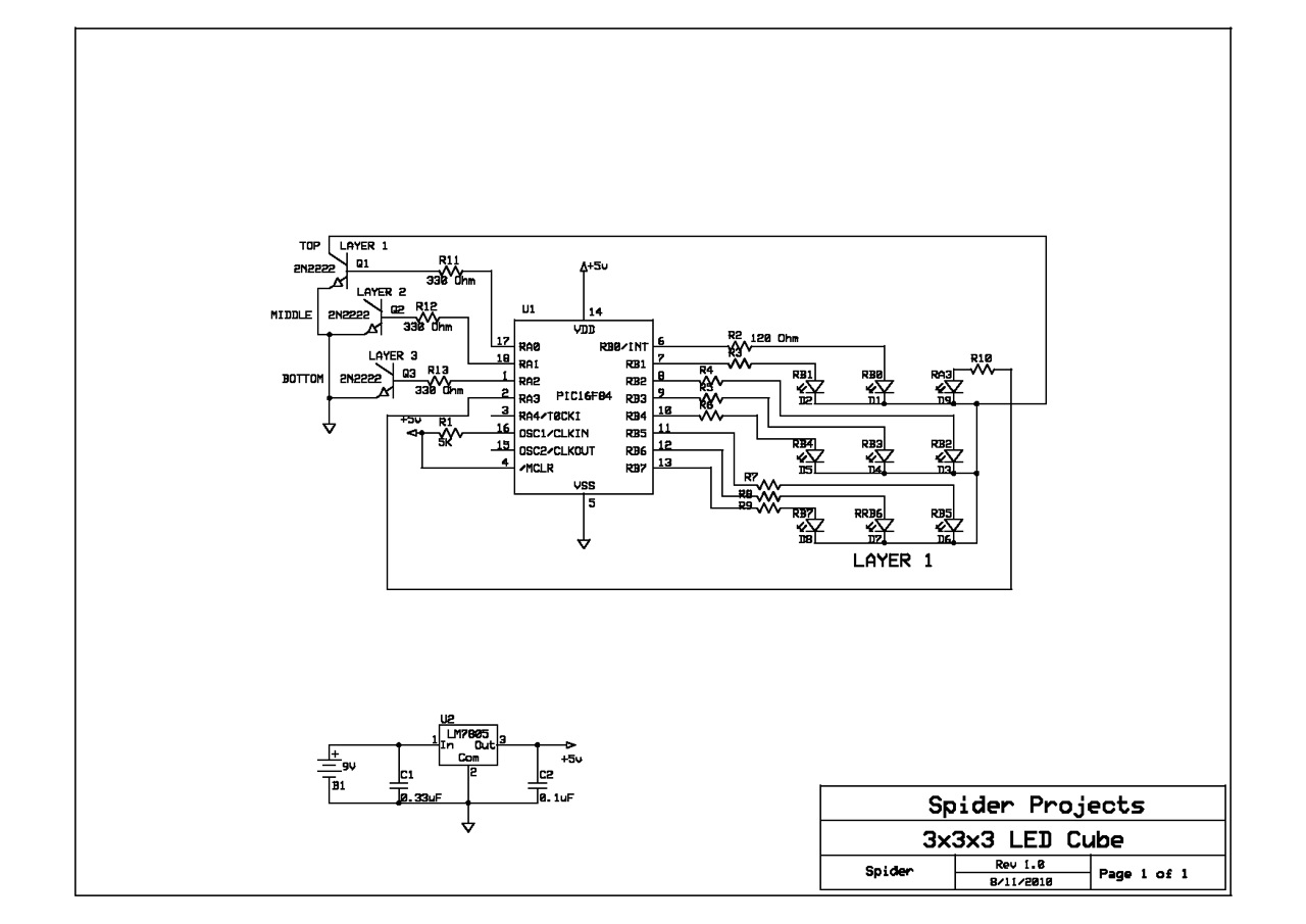
The schematic represents a basic LED cube design, which typically consists of multiple layers of LEDs arranged in a three-dimensional matrix. In this case, the first layer is illustrated, and the user is expected to replicate this structure for the subsequent layers, up to a total of three. The construction of each layer involves careful attention to the arrangement of the LEDs and the connections to the control circuitry.
Each LED in the cube is connected in a way that allows for multiplexing, a technique that enables the illumination of multiple LEDs without the need for a dedicated current limiting resistor for each individual LED. Instead, a single resistor is used for each column of LEDs, which helps to manage the current flow and prevent damage to the LEDs. This approach simplifies the circuit design and reduces the number of components required.
The multiplexing process involves rapidly switching between layers, illuminating one layer at a time while the others remain off. This creates the illusion of a fully lit cube as the human eye perceives the rapid changes in light. The control circuitry typically includes a microcontroller or similar device that manages the timing and sequencing of the signals sent to each layer and column.
It is essential to ensure that the power supply voltage and current ratings are suitable for the LEDs being used, as well as for the microcontroller. Proper grounding and signal integrity should also be maintained to avoid flickering or inconsistent illumination across the layers.
In summary, this schematic serves as a foundational guide for constructing an LED cube, emphasizing the importance of layer replication and the implementation of multiplexing techniques to achieve a visually appealing display.Found this schematic on the Internet and used it for my prototype cube. As you can see, only the first LED layer is shown, so you have to build it up to layer three without adult supervision. I only used the single current limiting resistor for each column knowing that I was attempting to multiplex..
🔗 External reference
Related Circuits
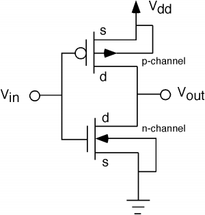
The fundamental issue presented is the perception that logic gates in a circuit seem to generate power from nothing, which contradicts the principles of physics. For instance, consider two NOT gates connected in series. It appears that the first...
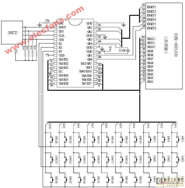
The ET6201 is a LED display control drive circuit with a duty cycle of 1/7 to 1/8. It features 11 segment output gates and 1 segment/gate output, along with a display memory, control circuit, and key scanning circuit, which...
Many applications do not require the precision of a digital or analog (bar graph) indicator but still benefit from more than a simple low/high signal. An example is a battery charge level indicator in a car. This basic circuit,...
When the preset is set to its maximum, the LED flashes approximately every half second. This flashing rate can be increased by using a larger capacitor value, for instance, changing from 10µF to 22µF will result in a flashing...

The two circuits illustrate the generation of low-frequency sine waves by shifting the phase of the signal through an RC network, enabling oscillation when the total phase shift reaches 360 degrees. The transistor circuit on the right produces a...
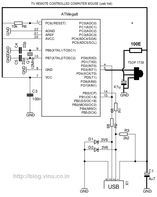
While lying in bed and watching movies on a laptop, the idea arose that having a remote control would simplify the tasks of pausing, playing, fast forwarding, rewinding, adjusting volume, and playing the next track without needing to approach...