
LED Traffic Lights for Games
The described circuit utilizes a 555 timer configured in astable mode to generate a pulse-width modulation signal that drives a 4017 decade counter IC. The 4017 is designed to sequentially activate its output pins, in this case controlling three LEDs that simulate a traffic light system. The output sequence typically follows the pattern of red, yellow, and green lights, mimicking standard traffic signal behavior.
The circuit begins with the 555 timer, which is set up with appropriate resistors and capacitors to determine the frequency and duty cycle of the output signal. The output from the 555 timer is connected to the clock input of the 4017 IC. As the timer generates pulses, the 4017 counts these pulses and sequentially activates its output pins (Q0, Q1, Q2) connected to the LEDs.
Each LED is connected through a current-limiting resistor to prevent excessive current flow, ensuring the longevity of the LEDs. The diodes used in the circuit are 1N4148, which are suitable for signal-level applications and help protect the circuit from reverse voltage conditions.
Powering the circuit can be achieved using either a 9V battery or a 12V battery/power supply, providing flexibility in terms of power sources. The design effectively demonstrates basic principles of digital electronics and timing circuits while serving a practical purpose in simulating traffic light operation.This schematic uses the 555 timer and the 4017 IC to drive 3 LED, to simulate the trafic lights. All diodes are iN4148. The circuit is operated with 9 volt battery or with a simple 12V battery or power supply. 🔗 External reference
Related Circuits
The circuit presented this month is a basic configuration of the very versatile 4017 IC Chip. In the most common use of the IC, it will turn on 10 separate outputs sequentially. Typically, the circuit is used to turn...
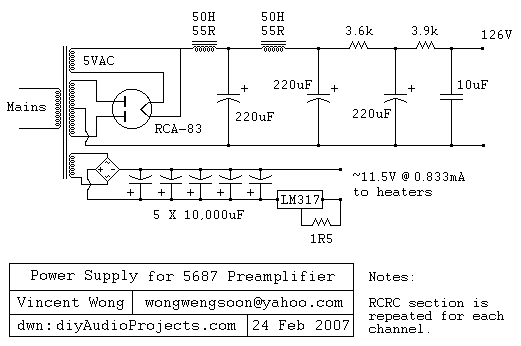
The RCA-83 rectifier utilizes 5VAC for the filament supply. The heaters for the 5687 tubes are powered by a full bridge rectifier consisting of MUR860 diodes, followed by five 10,000µF Elna capacitors. Current regulation is achieved through an LM317...
The following circuit is a six LED stereo VU display diagram that is constructed using the Dot/Bar Display Driver IC LM3915. This VU display should be connected before the amplifier module circuit. It can be connected at the pre-amp...
This project involves constructing an energy-efficient broad spectrum LED lamp system designed for indoor reflective room lighting. The lamp provides a broad color spectrum that closely resembles natural sunlight compared to fluorescent bulbs and white-only LEDs. The light output...
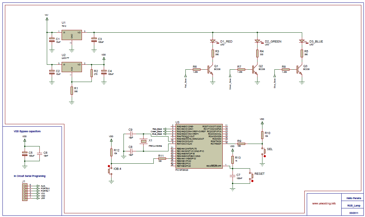
In this project it was used the Piranha Super-flux RGB Led of common anode, and the PIC18F25K20, in order to generate combinations of colors. It has two function modes, automatic that generate the color sequence that is stored in...
A motor spins the "propeller", and a small microprocessor keeps track of time and changes the pattern on seven LEDs with exact timing to simulate a 7 by 30 array of LEDs. It is an illusion, but it works...