
LED Counter with IC 4017
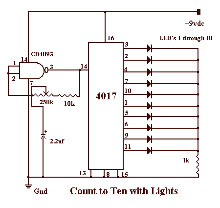
The circuit utilizes the 4017 decade counter IC, which is designed to sequentially activate its 10 output pins in response to clock pulses. Each output corresponds to a specific count, and once the count reaches 10, the sequence resets to output 0. The primary clock signal for the 4017 is generated using a NAND gate configuration from the CD4093, which serves as an oscillator. The frequency of this clock signal can be adjusted using a variable resistor (VR), allowing the output activation cycle to be set to 1 second.
The arrangement of the circuit involves connecting the output pins of the 4017 to individual LEDs, each corresponding to the outputs from 0 to 9. Each LED will illuminate sequentially with each clock pulse, creating a visual indication of the counting process. The circuit will continue to cycle through the outputs indefinitely until power is removed.
To ensure proper operation, it is essential to ground the unused pins of the NAND gates in the CD4093. Specifically, pins 5, 6, 8, 9, 12, and 13 should be connected to ground to prevent floating inputs, which could lead to erratic behavior or noise in the circuit. This grounding stabilizes the NAND gate operation and ensures reliable clock pulse generation.
Overall, this basic configuration serves as an effective demonstration of sequential output control using a decade counter and provides a practical application for visual indicators through LED activation.The circuit presented this month is a basic configuration of the very versatile 4017 IC Chip. In the most common use of the IC, it will turn on 10 separate outputs sequentially. Typically, the circuit is used to turn on a LED for certain time cycle. In the circuit shown the VR can be adjusted so that the clock output of the NAND gate will be 1 second. With this clock at 1 second intervals, the 4017 chip will turn on output # 0 to be high which will light and LED.
When clock pulse 2 is received a second later, output #1 will go high which will turn on LED2. This process will continue until all 10 outputs have gone on and then it will start all over again until you turn the power off. When building this circuit you should tie the left over pins of the other NAND gates in the CD4093 to ground.
Therefore, pins 5,6,8,9, 12 and 13 should be connected to ground. 🔗 External reference
Related Circuits
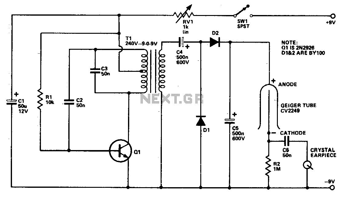
The Geiger tube requires a high voltage supply, which is formed by Q1 and its associated components. The transformer is connected in reverse; the secondary is configured as a Hartley oscillator, while R1 provides base bias. Diodes D1 and...
System Oscillator Crystal/Ceramic Oscillator. The following circuit combination of resistors, capacitors, and inductors depicts an equivalent circuit for a crystal or ceramic oscillator. The system oscillator, specifically a crystal or ceramic oscillator, utilizes a combination of passive components, including resistors,...
This circuit is designed as a toy to help young children learn to count. The power is activated by switch S1, and then switch S2 is closed, causing nine LEDs to flash slowly. When S2 is opened, the LEDs...
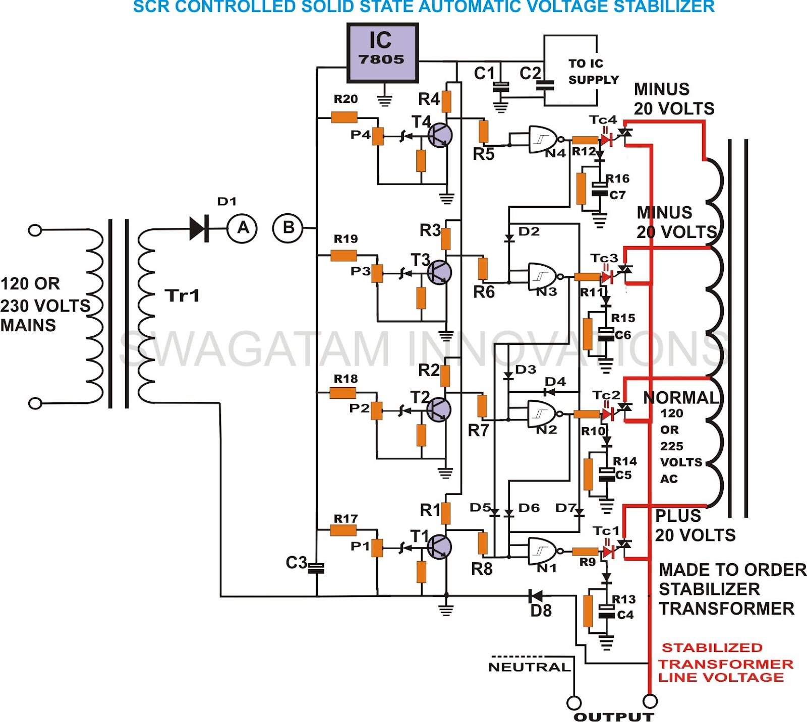
This unique and hard-to-find triac-controlled AC voltage stabilizer circuit has been specifically designed for efficient voltage stabilization. With a solid-state design, the voltage switching transitions are smooth, resulting in minimal wear and tear. The proposed circuit provides four-step voltage...
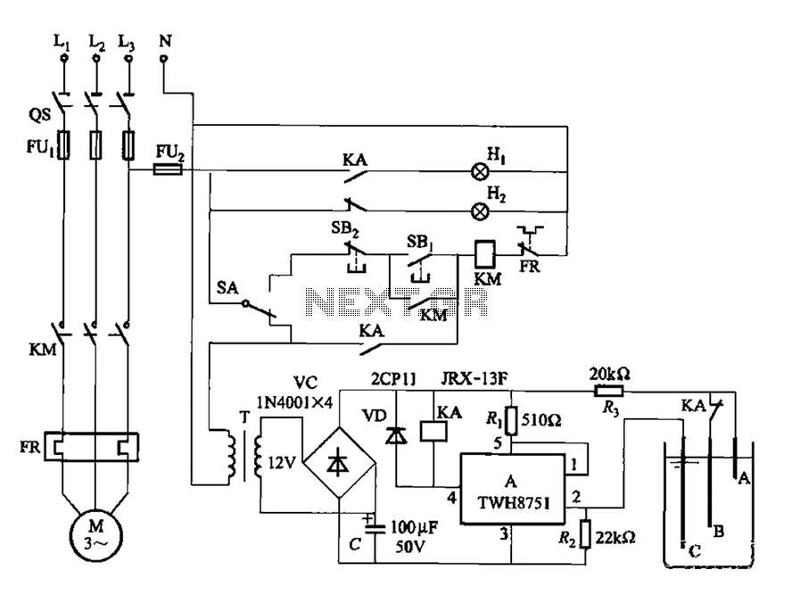
The power switch integrated circuit A features a straightforward design with high sensitivity, ensuring reliable operation. It is part of an automatic liquid level control circuit. When the water level at electrode B drops below 2 feet (0V), circuit...
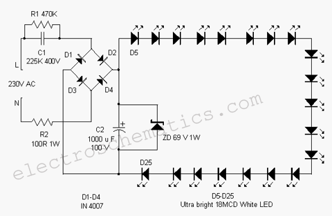
This white LED light illuminates the porch with cool white light. The circuit features a simple and energy-saving design. Its current consumption is practical. The white LED light circuit is designed to provide efficient illumination while minimizing energy usage. The...
Warning: include(partials/cookie-banner.php): Failed to open stream: Permission denied in /var/www/html/nextgr/view-circuit.php on line 713
Warning: include(): Failed opening 'partials/cookie-banner.php' for inclusion (include_path='.:/usr/share/php') in /var/www/html/nextgr/view-circuit.php on line 713