
LED VU meter circuit by transistor

The VU meter circuit is designed to visually represent the amplitude of an audio signal, providing a useful tool for audio engineers and sound technicians. This circuit typically consists of an analog meter, a rectifier, and a smoothing capacitor.
The integrated amplifier circuit receives the audio input signal, which is then amplified to the required level. The output from the amplifier is fed into the VU meter circuit. The rectifier converts the AC audio signal into a DC voltage, which is proportional to the audio signal's amplitude.
A smoothing capacitor is used to filter the rectified signal, ensuring that the VU meter needle responds smoothly to changes in audio levels, rather than jumping erratically. The VU meter itself is calibrated to display the audio level accurately, typically ranging from -20 dB to +3 dB, allowing for easy monitoring of audio performance.
In terms of components, the circuit may include resistors to set the sensitivity of the VU meter, a potentiometer for calibration, and possibly a transistor to drive the meter if the signal levels are low. Proper grounding and shielding are essential to minimize noise and interference, ensuring that the VU meter provides an accurate representation of the audio signal levels.
Overall, the integration of a VU meter with an audio amplifier circuit enhances the functionality of audio systems by providing real-time visual feedback on signal levels, facilitating better sound management and control.The V.U. meter that works with the integrated amplifier circuit.The signal will sound, the audio amplifier circuit into VU meter circuit.And will show the level.. 🔗 External reference
Related Circuits
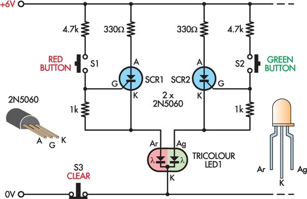
This is a modern twist on the classic game of noughts and crosses, utilizing nine 10mm tri-color LEDs arranged in a 3 x 3 grid. One player has nine red buttons while the other player has nine green buttons,...
The digital scoreboard circuit is designed to display numerical values ranging from 0 to 9 on a common anode 7-segment display. The circuit employs a 7-segment driver integrated circuit (IC), specifically the 74LS47 or 74LS247. A 555 timer IC...
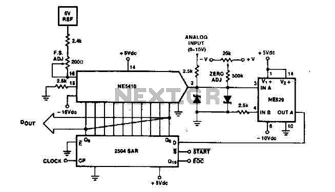
The time IO-bit conversion operates at 3.3 MHz with a clock signal. This converter utilizes a 2504 12-bit register in successive approximation mode, where the conversion signal for the short-cycle end is derived from the first bit utilized in...
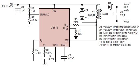
A straightforward dual 15-volt power supply electronic circuit can be created using the LT3512 switching regulator IC produced by Linear Technology. This basic 15-volt DC power supply operates with an input voltage range of 36 to 72 volts and...
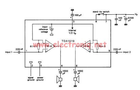
The TDA1519 circuit can deliver 2x6 watts output power. TDA1519 is an integrated class-B dual output amplifier in a 9-lead single in-line (SIL) plastic medium power package primarily developed for car radio applications. The TDA1519 is a robust integrated circuit...
A clock-controlled relay, also known as a time delay relay, allows for the automatic activation of a load, such as a water pump, at a predetermined time. This device utilizes a standard clock mechanism to trigger the circuit, enabling...