
Clock Controlled Relay
The clock-controlled relay circuit typically consists of several key components: a clock module, a relay, a power supply, and the load (in this case, the water pump). The clock module, which can be a digital or analog timer, is responsible for keeping track of time and determining when the relay should be activated.
Upon reaching the specified time, the clock module sends a signal to the relay. The relay acts as an electrically operated switch, allowing current to flow to the load when activated. In this configuration, the relay can handle higher voltage and current levels, making it suitable for controlling devices like water pumps, which may require more power than the clock module can provide directly.
The power supply is crucial for ensuring that both the clock module and the relay operate correctly. It must be rated to provide adequate voltage and current for all components in the circuit. Additionally, protective features such as diodes may be included to prevent back EMF from damaging the relay or clock module when the load is switched off.
To enhance the functionality of the circuit, it may be designed with adjustable time settings, allowing users to customize the activation time according to their specific needs. This flexibility makes clock-controlled relays ideal for various applications, including irrigation systems, aquariums, and automated home systems, where precise timing for device activation is essential.
Overall, the clock-controlled relay circuit is a practical solution for automating the operation of electrical loads based on time, improving efficiency and convenience in various settings.You can switch on a load such as Water pump automatically at the required time through this Clock Controlled Relay or also known as Time Delay Relay. It uses an ordinary clock to trigger the circuit to switch on the load 🔗 External reference
Related Circuits
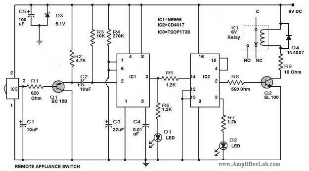
The circuit diagram of a remote-controlled appliance switch circuit includes two main components: IC1 (NE 555) and IC2 (CD 4017). The remote-controlled appliance switch circuit is designed to allow users to control electrical appliances wirelessly. The heart of this circuit...
This document serves as a compilation of design notes, providing practical details as construction progresses, along with some photographs that will be included in due course. Currently, it functions as a progress report, blending immediate plans with actual construction,...
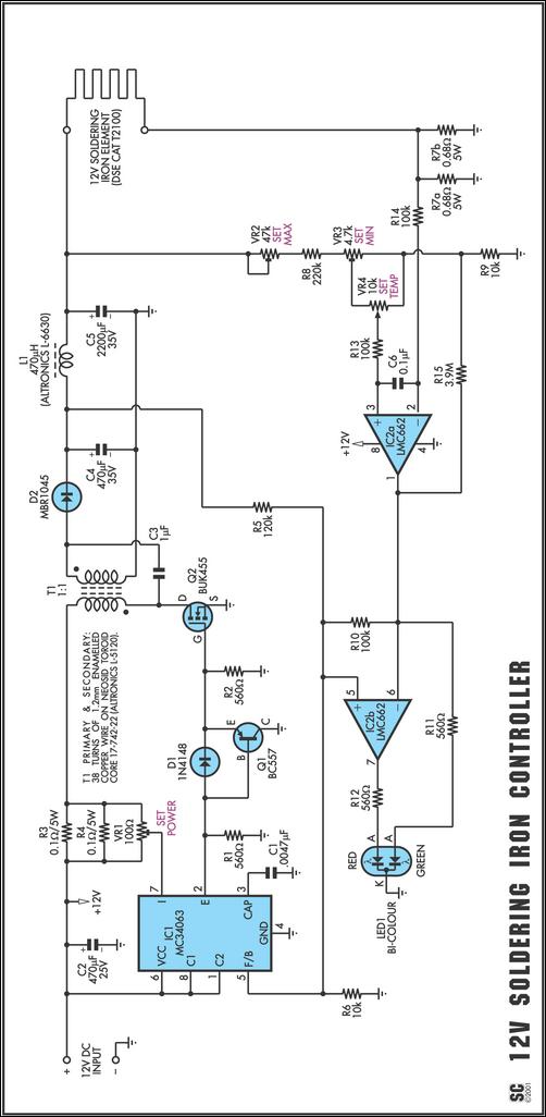
One reason commercial soldering stations are costly is that they typically use soldering irons equipped with built-in temperature sensors, like thermocouples. This circuit design eliminates the necessity for a specialized sensor by directly sensing the temperature of a soldering...
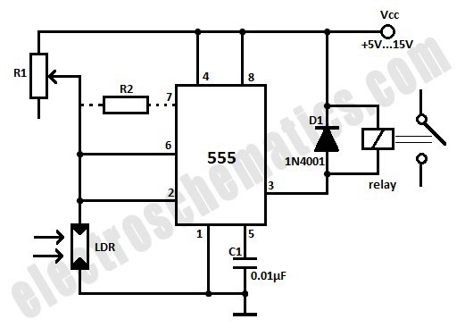
This light-activated relay circuit utilizes the 555 timer integrated circuit (IC) and a light-dependent resistor (LDR) to create a light-sensitive relay suitable for applications such as intruder alarm systems or automatic lamp control at sunset and sunrise. The potentiometer...
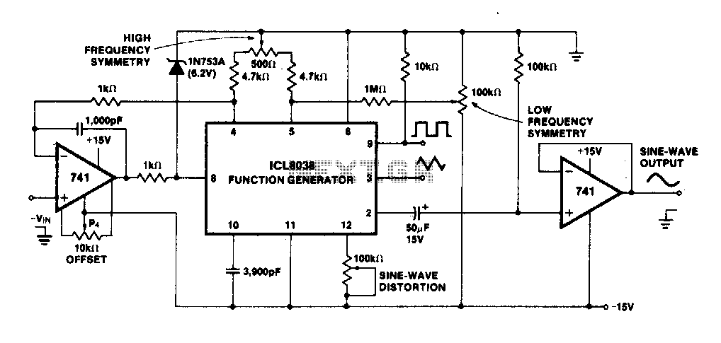
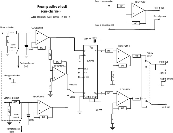
The linearity of the input sweep voltage in relation to the output frequency is significantly enhanced by utilizing an operational amplifier. The utilization of an operational amplifier (op-amp) in electronic circuits is a common practice to improve the linearity of...
.jpg)
This tutorial demonstrates how to utilize an Arduino to display the current time and date on an optional LCD screen and in the Arduino IDE serial monitor. A PCF8563 real-time clock (RTC) integrated circuit (IC) is employed to provide...
Warning: include(partials/cookie-banner.php): Failed to open stream: Permission denied in /var/www/html/nextgr/view-circuit.php on line 713
Warning: include(): Failed opening 'partials/cookie-banner.php' for inclusion (include_path='.:/usr/share/php') in /var/www/html/nextgr/view-circuit.php on line 713