
LEDs and resistors circuit

An LED operates effectively within a specific range of voltage and current. The forward voltage drop across the LED is typically around 2V, but this can vary depending on the specific type of LED. The forward current is usually around 20mA, which is the standard for many common LEDs. It is important to consult the LED's datasheet for precise specifications to ensure proper operation.
In a basic circuit design, the inclusion of a current-limiting resistor is vital. This resistor serves to protect the LED from excessive current that could lead to failure. The resistor should be placed in series with the LED to maintain the desired current flow through the circuit. The calculation for the resistor value involves subtracting the LED's forward voltage from the supply voltage and dividing the result by the desired current.
For example, with a 12V power supply and an LED with a forward voltage of 2V and a desired current of 20mA, the calculation is as follows:
1. Voltage across the resistor = Supply Voltage - LED Voltage = 12V - 2V = 10V.
2. Using Ohm’s Law: R = V/I = 10V / 0.02A = 500Ω.
Since 500 ohms is not a standard resistor value, choosing the closest available value, such as 510 ohms, is appropriate.
When using a 510-ohm resistor, the actual voltage drop across the LED can be calculated to ensure it remains within safe operating limits. By applying Ohm's Law again, the voltage drop across the resistor can be determined, which allows for verification of the LED's performance in the circuit. This careful consideration of resistor values and LED specifications contributes to the longevity and reliability of the LED in various applications.An LED is an electronic component or semiconductor to be more precise. This means that it is neither a conductor (something that conducts electricity) or insulator (something that does not conduct electricity) - it is something in between. LED is an acronym for Light Emitting Diode. Simply put, a diode is a device that only allows current flow in one direction and blocks it flowing in the other direction. The LED is a diode that emits light when current flows through it in the correct direction. This also means that the LED is a polarized device - it has a positive and negative side (also known as anode and cathode respectively). If it is not the right way around in the circuit to be used, current will not flow and no light will be emitted.
LEDs also don`t like to be installed the wrong way around. One a certain voltage level is reached, the LED can self-destruct if installed back-to-front. Each leg of an LED is identified by its length. The longer leg is known as the anode or positive side The shorter leg is known as the cathode, or negative side. Normally, looking from the top, there is a "flat" side of the LED - this also signifies the cathode. To use an LED, you should find out the specifications about their performance. This will show things like viewing angle, voltage, current required, possibly the light wavelength emitted and a few other parameters.
The main ones are voltage and current. As a general rule of thumb, the voltage could be considered as 2V, and current considered as 20mA (milli-amps, or 0. 02A). If you don`t know the particular specifications of the LED you are using (it could be 1. 8V or 2. 2V or 30mA for example), use the above rule-of-thumb figures. For a basic circuit of a single LED and power source, a resistor (a semiconductor that has a known value of resistance) is required to limit the current and reduce the voltage so that the LED can operate correctly.
Too much voltage or too much current can either destroy the LED in a split second, or greatly reduce its life span. I prefer to slightly under-rate the LED to prolong its life span. The power source to the LED should also be regulated. That means that the voltage output (or in some cases the current output) is controlled and does not fluctuate under varying load conditions.
If the power source is not regulated, the small fluctuations and glitches in power can shorten the life of the LEDs in extreme cases. A simple circuit to operate the LED from a known power source, requires only a resistor in series with the LED.
Consider that we have a 12V DC power source, a common variety LED (2V, 20mA). All we need to do is calculate the resistor value. As the components will be wired in series, the current flow through all components is equal. So we have a known LED voltage drop (2V) and a desired current flow of 20mA (or slightly less), we can now calculate the resistor value with Ohm`s Law. That is Voltage (V) = current (I) x resistance (R). As we are looking for resistance, the formula will be resistance (R) = voltage (V) divided by current (I).
Since we have 12V as the supply voltage and the LED will "drop" 2V across it, that leaves 10V "drop" across the resistor and a current of 20mA to flow through it. So we can find our resistance value by inserting our known values in the Ohm`s law equation to give us: R = 10V/20mA (resistance = voltage divided by current) Or R = 10/0.
02 which gives us 500ohms. If you look up the resistors available from your electronics supplier, 500ohms is not a standard value. So we look for the next highest value (or next lowest if it is very close). The available values are 470ohm, 510ohm or 560ohm. 510ohm is the closest match and should be used. If we want to find out the actual voltage drop across the LED with a 510ohm resistor, we can use Ohm`s law again.
This time we have resistance and current so the formula becomes V = I x R. That is V = 0. 02 x 510. That giv 🔗 External reference
Related Circuits
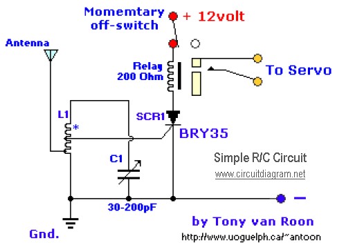
The diagram illustrates a straightforward and efficient receiver designed for activating garage doors, starter motors, alarms, warning systems, and various other applications. The silicon-controlled rectifier (SCR) utilized in this circuit features an exceptionally low trigger current of 30 µA,...
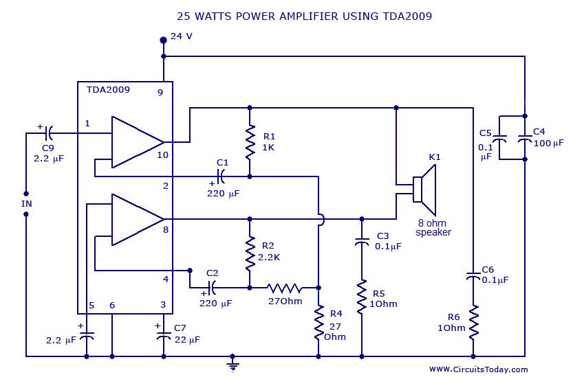
Power amplifier circuit diagram with schematics. This simple audio power amplifier circuit is designed for 25 watts output power using TDA 2009 IC, which has two channels (stereo), 12.5 W for each channel. The described power amplifier circuit utilizes the...
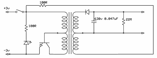
Free energy motors and generators are available for purchase, featuring plans for overunity devices. These devices resemble oscillators used in Joule thief circuits, although there may be some errors present in the designs. However, the concept remains clear. Free energy...
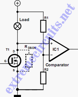
In applications where a MOSFET is used to switch a load, it is relatively straightforward to incorporate short-circuit or overload protection. This can be achieved by utilizing the internal resistance RDS(ON), which generates a voltage drop proportional to the...
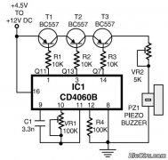
This is a simple home telephone ringtone generator circuit constructed using only a few electronic components. It generates a simulated telephone ringtone and requires a DC supply voltage ranging from 4.5V to 12V. This circuit can be used in...
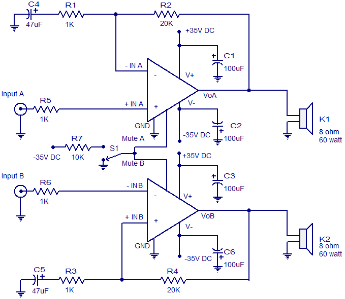
The circuit diagram presented is for a 2 x 60 Watt stereo amplifier utilizing the LM4780 from National Semiconductors. The LM4780 is an excellent audio amplifier integrated circuit capable of delivering 60W RMS power output per channel into 8-ohm...