
Power AmplifierCircuit and Schematics for 25 Watts-IC TDA2009

The described power amplifier circuit utilizes the TDA 2009 integrated circuit, a popular choice for audio amplification applications due to its robustness and efficiency. This circuit is configured to deliver a total output power of 25 watts, effectively splitting this power into two channels, with each channel capable of providing 12.5 watts of audio output.
The TDA 2009 IC operates with a supply voltage range of 12V to 18V, making it suitable for various audio applications. The circuit typically includes the necessary passive components, such as resistors and capacitors, to stabilize the amplifier's performance and improve sound quality.
Input signals are fed into the amplifier through the appropriate input terminals, and the output is connected to speakers or other audio devices. The design may also incorporate features such as thermal protection and short-circuit protection to enhance reliability and prevent damage under adverse conditions.
The schematic representation of this amplifier circuit would include the TDA 2009 IC at the center, with connections for power supply, input, and output clearly delineated. Additional components such as coupling capacitors and feedback resistors may be included to optimize the amplifier's frequency response and reduce distortion.
Overall, this power amplifier circuit is an effective solution for driving stereo speakers in various audio applications, providing clear sound reproduction with sufficient power output for home audio systems or small public address systems.Power amplifier circuit diagram with schematics. This simple audio power amplifier circuit is designed for 25 watts output power using TDA 2009 IC -which has two channels (stereo),12.5 W each channel.. 🔗 External reference
Related Circuits
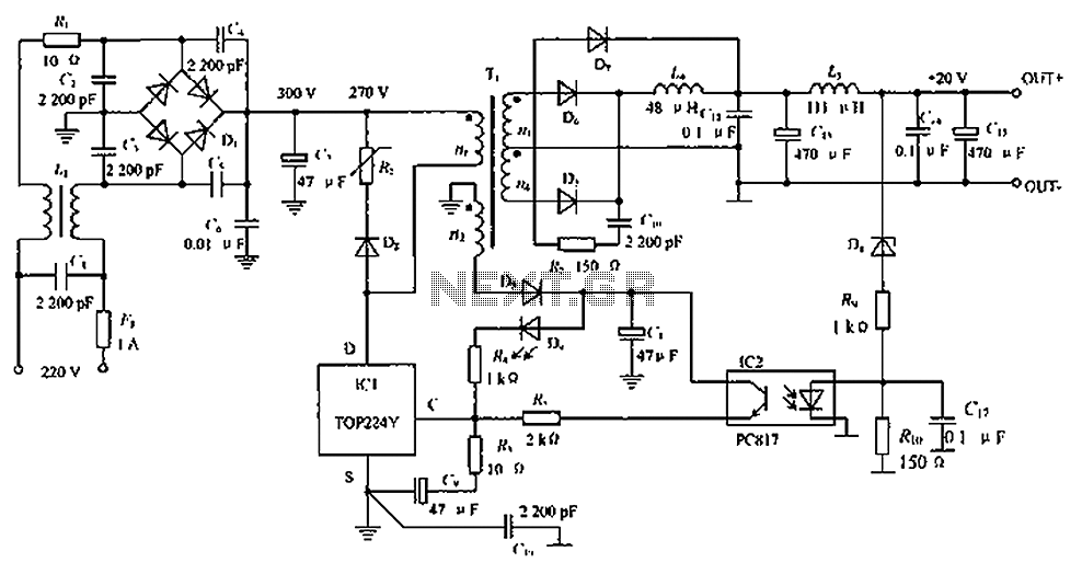
The circuit depicted in the figure is designed to achieve a higher power output by modifying specific components. On the left side of the figure, components R1, L1, D1, and capacitors C1 to C7 form a conventional filtering and...
This class-D audio amplifier is suitable for TV and home stereo systems. The TDA7882 integrated circuit (IC) provides a class-D audio amplifier solution. Since this IC has a single channel output, two units are required for stereo applications. The...
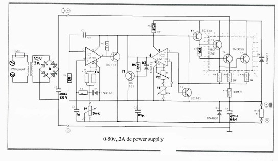
A variable power supply designed for laboratory use. It utilizes two integrated circuits (ICs) to provide adjustable output voltage and current. This variable power supply is engineered to meet the diverse needs of laboratory applications, offering flexibility in output voltage...
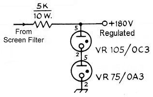
The power transformer features three secondary windings: 720V at 120mA center-tapped for the plate and screen supplies, 6.3V at 3.5A for the tube filament and bias power supply, and 5V at 3A (unused). Since the 5V secondary is not...
As readers may know, there are several power amplifier projects, including two that utilize integrated circuit (IC) power amplifiers, commonly referred to as power op-amps. Both of these projects have gained popularity, and this new project is not intended...
The first prototype PCB has been completed, but concerns arise regarding the heat generated when utilizing the BMS at maximum power in an ultralight hybrid electric vehicle application. At 30A continuous and 50A burst, nearly 20W of loss occurs....