
Light alarm schematic circuit diagram
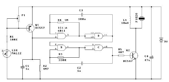
This light alarm circuit employs a Darlington phototransistor, which is sensitive to light changes, making it suitable for detecting when a drawer is opened. The core functionality relies on the interaction between the MAL12 phototransistor and the BC557 transistor, where the presence of light causes the BC557 to conduct. This action sends a high signal to the inputs of the 14011 NAND gate, initiating oscillation and triggering the alarm.
The design allows for flexibility in output configuration; the alarm can be connected to a relay for controlling higher power devices or a triac for AC applications. The choice of components reflects a balance between sensitivity and reliability, ensuring that the alarm system responds promptly to the opening of the drawer.
The delay mechanism provided by the capacitor and resistor creates a brief continuation of the alarm sound even after the light is no longer detected. This feature can be particularly useful in scenarios where immediate silence is not desired, allowing users a moment to react or address the situation. The values of the capacitor and resistor can be adjusted to modify the duration of the alarm sound, providing further customization for specific applications.
Overall, this light alarm circuit is an effective solution for alerting users to the status of a drawer or similar enclosure, enhancing security and awareness in various environments.This light alarm schematic circuit is designed using some common electronic parts, as you can see in the circuit diagram bellow. This light alarm schematic circuit project will sound as soon as the drawer is opened and light falls on the Darlington phototransistor.
The output alarm may be redesigned to activate a relay or triac. The 14011 quad, 2 input, NAND gate is wired up to oscillate when the input to it goes high, that is the BC557 transistor turns on after light is detected by the MAL12. After the alarm has started and it is put back into dark conditions, alarm will continue to sound for about 3 - 5 seconds.
This is due to the 1uF capacitor and 4M7 resistor which keep the input to the 14011 high. 🔗 External reference
Related Circuits
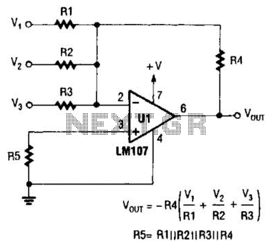
The output of Ul is the sum of Vv, multiplied by the ratio of Rx to Rv, RJRV, and respectively. Resistors R1, R2, and R3 are selected as required for individual gains. Additionally, R4 influences the gain of all...

The circuit utilizes the ISO120 and INA105 instrumentation amplifiers to create a battery monitoring system for a 600V battery setup composed of 50 series-connected 12V batteries. This circuit is designed to detect charging and discharging conditions to prevent overcharging...
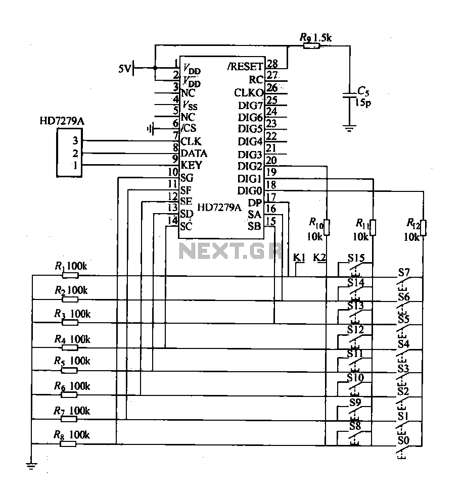
The design includes a front panel featuring buttons for setting 10 number keys (0-9), along with additional keys such as "Move Down," "Health," "Enter," "Recover," and a "Door Key," totaling 16 keys. The system also incorporates an interior door...
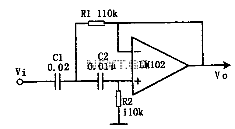
This document presents an active low-pass filter circuit with a cut-off frequency (fc) of 10 kHz. The circuit allows for various values for the ratios of resistors R1 and R2, as well as capacitors C1 and C2. Specifically, it...
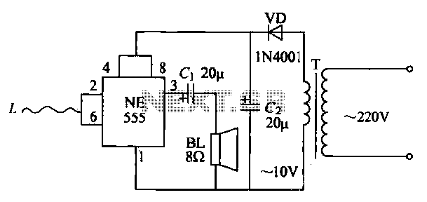
The manpower inductive alarm circuit is simple and practical. When a person's hand approaches the sensing line, the alarm emits a sound, making it suitable for male electrical burglar alarms. The induction line L is approximately 50 cm long....
Constantly changing light and sound analog controller circuit 04 The circuit designated as the "Constantly Changing Light and Sound Analog Controller Circuit 04" is designed to modulate both light and sound outputs in a dynamic manner. This type of...