
Active low-pass filter LM102 schematic
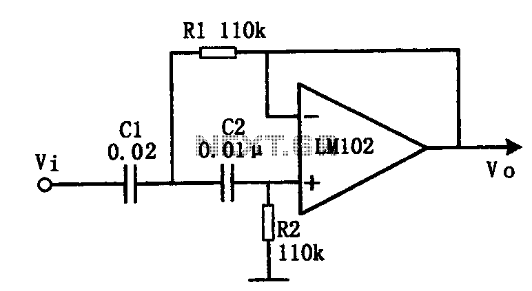
The active low-pass filter circuit is designed to attenuate frequencies above the cut-off frequency while allowing lower frequencies to pass through with minimal attenuation. The cut-off frequency, defined by the formula fc = 1/(2πRC), is determined by the values of the resistors and capacitors used in the circuit. In this case, the chosen cut-off frequency of 10 kHz indicates the point at which the output signal begins to decrease in amplitude relative to the input signal.
When configuring the circuit, the selection of resistor and capacitor values is crucial. For instance, if R1 is set equal to R2, it maintains a balanced voltage divider, which is essential for stable operation. The relationship between C1 and C2, where C1 is double the capacitance of C2, allows for flexibility in tuning the filter's response characteristics. This configuration can be particularly useful in applications where precise filtering is required, such as in audio processing or signal conditioning.
Alternatively, setting C1 equal to C2 and R1 equal to twice R2 creates a different filter response, which can be useful in scenarios where a specific phase shift or gain is desired. The ability to adjust these parameters provides versatility in designing filters tailored to specific frequency responses or application requirements.
Overall, the active low-pass filter circuit is a fundamental building block in electronic design, providing essential functionality in a wide range of applications, from audio systems to data acquisition and signal processing. Careful consideration of component values and configurations will yield optimal performance in filtering unwanted high-frequency noise while preserving the integrity of the desired low-frequency signals.Shown for the active low pass filter circuit. Cut-off frequency fc of the circuit = 10kHz. Circuit, R1 and R2 ratio and the ratio of C1 and C2 can be various values. This circuit uses R1 = R2 and C1 = 2C2. Using C1 = C2 and R1 = 2R2 can.
Related Circuits
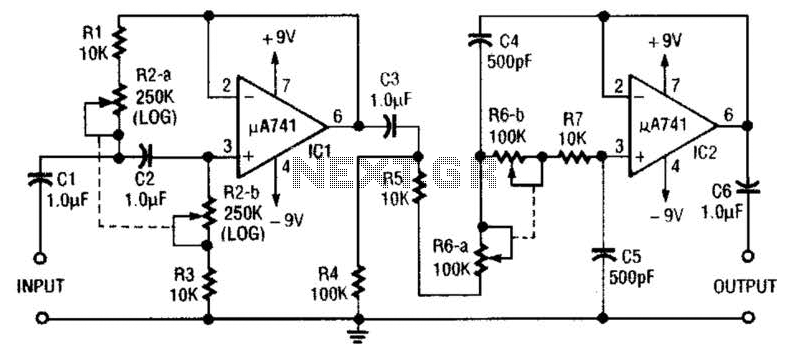
This circuit is a variable audio bandpass filter that features a low cutoff adjustable from approximately 25 Hz to 700 Hz and a high cutoff adjustable from 2.5 kHz to over 20 kHz. The roll-off is set at 12...
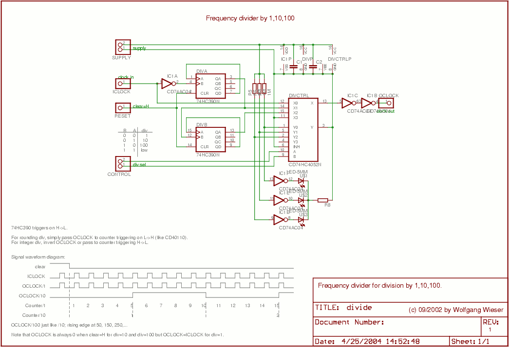
The divider design is straightforward. Users can select a division factor of 1, 10, or 100, or opt for no output (tied low) through the CONTROL input connected to the analog multiplexer HC4052. The design utilizes AC04 to drive...

This car audio amplifier circuit is based on the LA47536 audio amplifier integrated circuit designed by Sanyo. This audio amplifier circuit is specifically designed for car audio power amplifiers. The LA47536 car audio amplifier IC features four output channels...
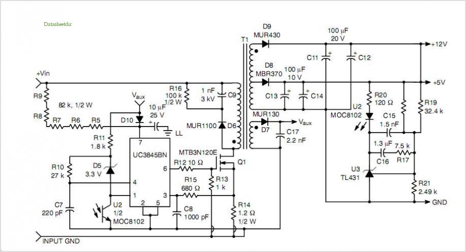
This post summarizes the work of experts in switching power supply schematic diagrams who are thoroughly knowledgeable about all aspects of the subject. Switching power supplies are crucial components in modern electronic devices, providing efficient voltage regulation and power conversion....
A schematic for a 16-channel passive summing mixer has been developed based on information gathered from various forums and online resources. The 16-channel passive summing mixer is designed to combine multiple audio signals into a single output while maintaining the...
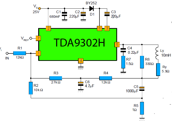
The TDA9302H is a monolithic integrated circuit housed in a HEPTAWATTTM package. It functions as a high-efficiency power amplifier designed for direct drive vertical deflection coils in television yokes. This component is suitable for use in both color and...