
AC LED drive circuit
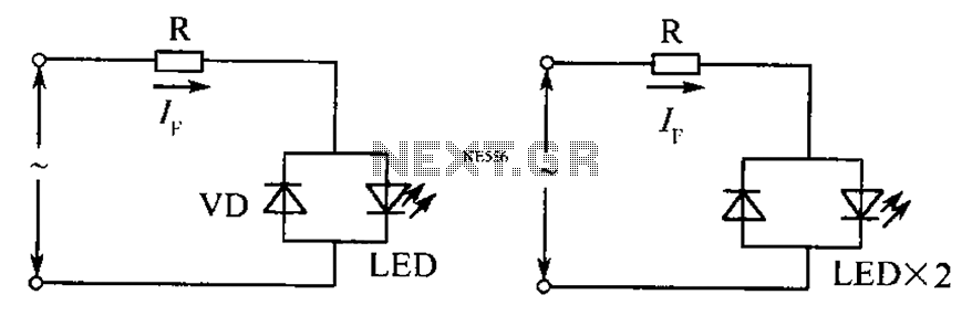
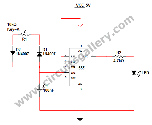
The described circuit is designed to accommodate both AC and DC power sources, ensuring reliable operation regardless of polarity. It incorporates a current limiting resistor, denoted as R, which plays a critical role in protecting the circuit from excessive current that could potentially damage components. The resistor's value is calculated in relation to the root mean square (RMS) voltage of the AC supply, which is essential for ensuring that the circuit operates within safe current limits.
In practical applications, the circuit can be employed in various devices where power supply polarity may be uncertain. This feature is particularly advantageous in environments where power connections may be made incorrectly, as it mitigates the risk of damage to sensitive electronic components. The design may also include additional protective elements such as diodes to prevent reverse polarity damage and to ensure that the circuit remains functional under varying conditions.
When designing the current limiting resistor, it is important to consider the maximum expected RMS voltage and the desired current limit for the application. The resistor value can be calculated using Ohm's law, where the resistance R is equal to the voltage (V) divided by the current (I). This relationship ensures that the circuit operates efficiently and safely, maintaining the integrity of both the power supply and the connected loads.
Overall, the circuit's ability to handle reversed polarity and its adaptability to both AC and DC drives make it a versatile solution in electronic design, suitable for a wide range of applications. As shown, still work in the case of unknown polarity of the voltage or the power supply polarity is reversed. And DC Drives as AC drives, the current limiting resistor R whose value is: where, AC RMS voltage.
Related Circuits
Switching regulator subsystems are designed for use as DC to DC converters. The 3V to 40V DC converter circuit utilizes switching regulators, which are increasingly favored over linear regulators due to the demand for higher conversion efficiency in modern...
More: An electronic schematic is a representation of the components and connections within an electronic circuit. It serves as a blueprint for constructing electronic devices, allowing engineers and technicians to visualize how components interact and function together. The schematic...
Many households are still equipped with tube-type television sets. If there is a desire to connect one of these large televisions to a stereo system to enhance the sound quality... To connect a tube-type television to a stereo system, it...
How to change the brightness of an LED. Are LED lights dimmable? Is it possible to adjust the brightness of LEDs? An LED is essentially a diode; when the forward voltage exceeds 0.7 volts, it begins to emit light,...
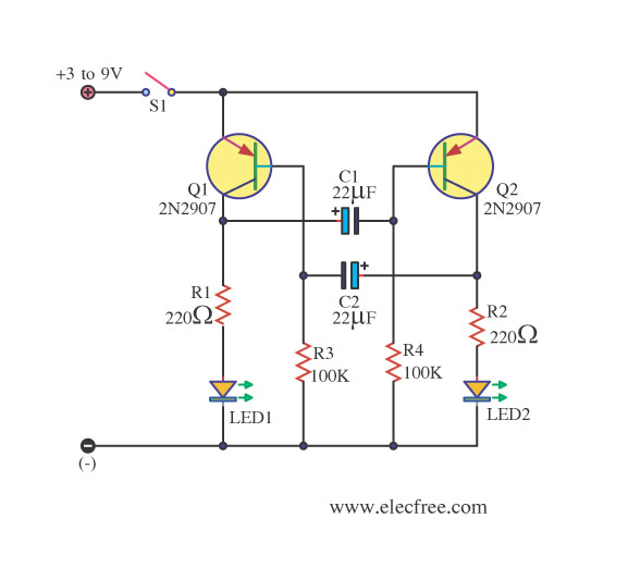
This circuit operates as a free-running multivibrator, resembling a flip-flop. It continuously oscillates on its own. The transistors Q1 and Q2 are PNP types, commonly used models include the 2N3906 and 2N2907. Resistors R1 and R2 limit the current...
This circuit is designed for children's entertainment and can be installed on bicycles, battery-powered cars, motorcycles, as well as on models and various games and toys. When switch SW1 is positioned as depicted in the circuit diagram, it generates...