
3V to 40 Volt DC Converter Circuit Schematic Diagram
The MC34063 series is a versatile and efficient solution for DC to DC conversion, capable of handling various voltage levels and configurations. The internal components of the MC34063 facilitate seamless operation in diverse applications, such as battery-operated devices, power supplies for sensors, and automotive electronics. The temperature-compensated reference ensures stable output voltage across varying temperatures, which is critical for maintaining performance in real-world scenarios.
The comparator within the MC34063 monitors the output voltage and adjusts the switching duty cycle to maintain the desired output level, providing a robust feedback mechanism. The controlled duty cycle oscillator allows for efficient switching, reducing power loss and improving overall efficiency compared to linear regulators. The active peak current limit circuit protects the device and the load from excessive current, enhancing reliability and safety during operation.
In terms of implementation, the MC34063 can be configured for different modes of operation. For step-up (boost) configurations, the circuit can increase the input voltage to a higher output voltage, which is useful in applications where the input voltage is lower than the required output. Conversely, in step-down (buck) configurations, the circuit can reduce the input voltage to a lower output voltage. Additionally, voltage-inverting configurations allow for generating negative output voltages, expanding the range of applications.
The 8-pin dual in-line package makes the MC34063 easy to integrate into existing designs and prototyping setups. Its compact size and efficiency make it suitable for modern electronic devices that require space-saving solutions without sacrificing performance. Overall, the MC34063 series represents a reliable choice for engineers seeking to implement efficient DC to DC converters in their designs.Switching regulator subsystems intended for use as dc to dc converters. 3V to 40 Volt DC Converter circuit | The use of switching regulators is becoming more pronouncedover that of linear regulators because the size reductions innew equipment designs require greater conversion efficiency. Another major advantage of the switching regulator is that i thas increasednapplication flexibility of output voltage. The output can be less than, greater than, or of opposite polarityto that of the input voltage. The MC34063 series is a monolithic control circuitcontaining all the active functions required for dc to dc converters. This device contains an internal temperaturecompensated reference, comparator, controlled duty cycleoscillator with an active peak current limit circuit, driver, and a high current output switch.
This series was specificallydesigned to be incorporated in step up, step down andvoltage inverting converter applications. These functionsare contained in an 8 pin dual in line package. You are reading the Circuits of 3V to 40 Volt DC Converter Circuit And this circuit permalink url it is
🔗 External reference
Related Circuits
This device generates high-voltage pulses that disrupt muscles and the nervous system, causing mental confusion in anyone who comes into contact with it. It can be utilized against aggressive animals or attackers; however, it is important to note that...
This circuit is a small digital roulette. It consists of an oscillator IC1, a counter IC2, and transistors Q1-7 that drive the common cathode display DSP1. The power supply typically comes from a 9V battery, but it can also...
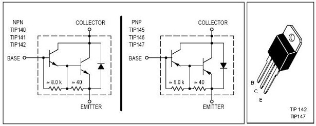
This is an economical 150 Watt amplifier circuit featuring two Darlington power transistors, TIP 142 and TIP 147. The circuit is capable of delivering up to 150 W RMS to a 4 Ohm speaker, providing substantial audio output. The...
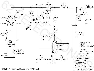
The following circuit illustrates the SciTech PS-3R Power Supply Circuit. Features include 13.8V DC output, 5 Amps surge capability, and a constant output of 3 Amps. Components include a transistor and others. The SciTech PS-3R Power Supply Circuit is designed...
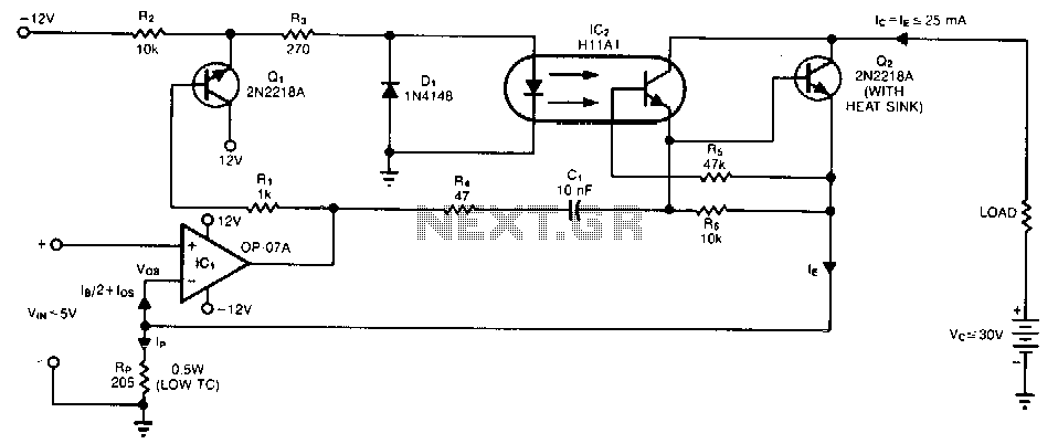
A single programming resistor (Rp) provides an output current range of approximately six decades. It is important to note that the temperature coefficient (TC) of this resistor can introduce potential errors, as it dissipates 125 mW when the junction...
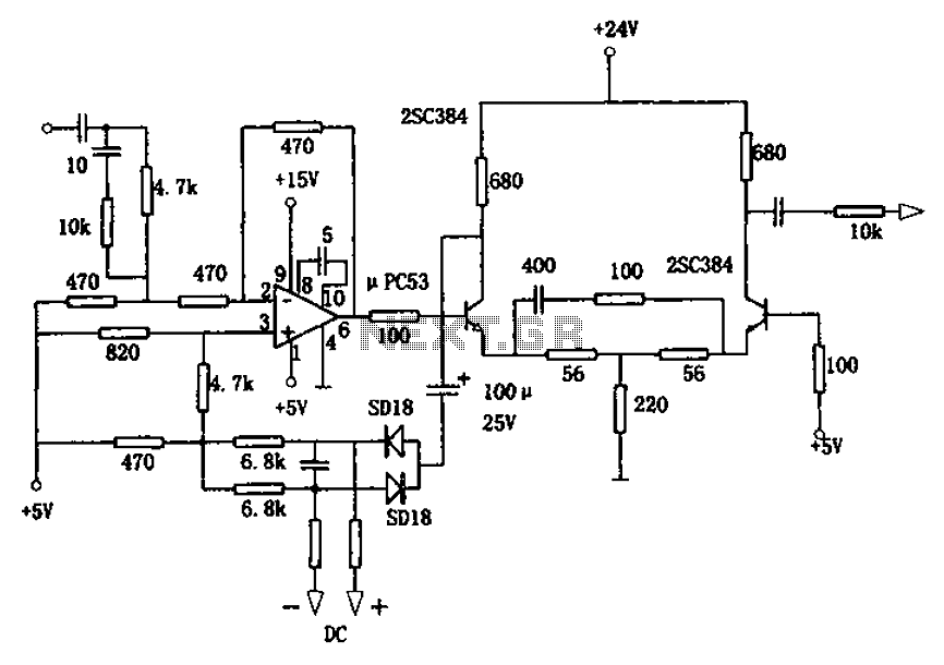
The circuit is designed for a broadband linear detection application with a bandwidth of 10 MHz. It serves as a millivoltmeter measuring instrument suitable for frequencies exceeding 10 MHz. The circuit features a linear detector utilizing operational amplifiers, specifically...