
Light Pollution Meter
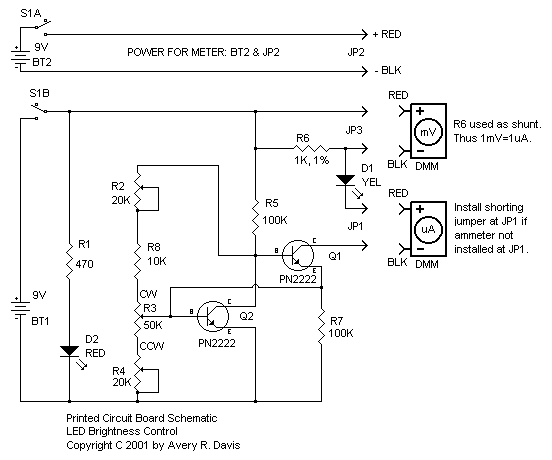
The described circuit utilizes a transistor to implement feedback control, enhancing the stability and accuracy of the output current. The inclusion of two resistors serves to set the gain of the transistor and define the operational range of the control system. By adjusting the values of these resistors, the circuit can be fine-tuned to achieve a desired output range, which in this case is specified as 2 to 30 microamps.
The single-turn potentiometer allows for precise adjustments within this range, enabling the user to easily set the output current as needed. This feature is particularly useful in applications requiring fine control over current levels, such as in calibration processes or sensitive measurements.
The entire assembly is housed within a compact plastic enclosure, which not only provides protection for the components but also enhances portability. The integration of banana plugs at the bottom of the box facilitates direct connection to a Digital Multimeter (DMM), eliminating the need for additional wiring or connectors. This design choice simplifies the user experience by reducing clutter and streamlining the measurement process.
Overall, this circuit design effectively combines functionality with convenience, making it a practical tool for electronic measurements and control applications.My circuit adds a transistor, to add feedback, and two resistors, to tailor the range of the control, with the result that a single-turn potentiometer gives a control range of about 2 to 30 microamps. I installed my circuit in a small plastic box, and mounted banana plugs on the bottom of the box spaced so that they would plug directly into the DMM.
This combines the controller with the DMM, so there is one less thing to hold. 🔗 External reference
Related Circuits
This circuit is continuously connected to a mains socket and is designed to trickle charge nickel-cadmium (Ni-Cd) batteries. In the event of a power outage, the lamp automatically turns on. Alternatively, an alarm sounder can be selected instead of...

The generated alternating current (AC) at both ends of the voltage is adjusted after being rectified to supply the motor armature windings, allowing for speed adjustments of a 15W lamp. It is noteworthy that despite the freewheeling role of...
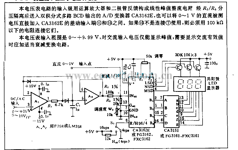
The input stage of this voltmeter circuit utilizes an operational amplifier and diode feedback to create a linear peak value rectifier circuit. A partial pressure isolation through resistors R1 and R2 directs the signal to a dual multi-channel BCD...
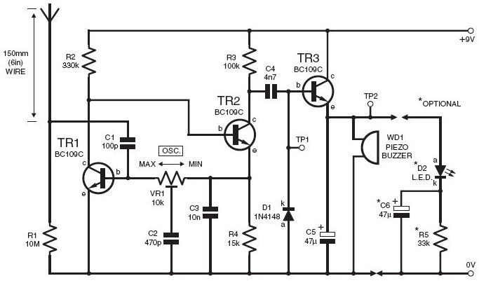
This DIY lightning detector circuit is a highly sensitive static electricity detector that provides an early warning of approaching storms from inter-cloud discharges well before an earth-to-sky return strike occurs. An aerial (antenna) made from a short length of...
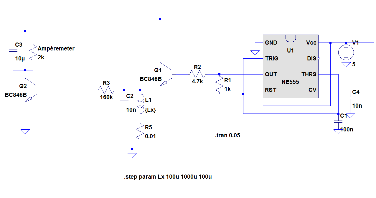
The objective of the project is to construct a simple, low-cost inductance meter. The primary components of the project include an IC 555, a transistor, a resistor, and a capacitor. The inductance meter designed in this project utilizes the IC...
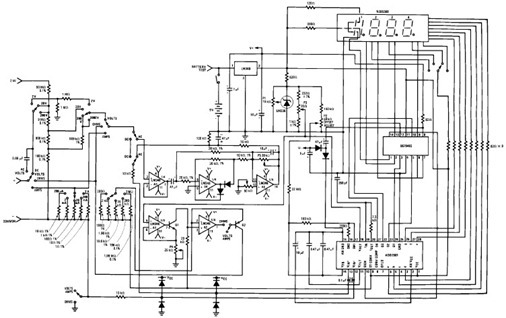
The following circuit illustrates the design of a simple digital multimeter circuit diagram. This circuit employs the ADD3501. Features include the combination of voltage measurements, among others. The circuit design for a simple digital multimeter utilizing the ADD3501 integrates several...