
Lighting Circuits Connections for Interior Electrical Installations
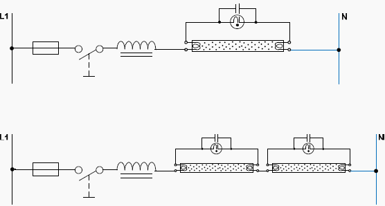
The lighting circuit design begins with the main distribution panel, which serves as the central hub for electrical distribution. Each lighting circuit is equipped with three conductors: the phase conductor, which carries the current; the neutral conductor, which completes the circuit; and the ground conductor, which provides safety by directing any fault current away from users and equipment.
The phase conductor is typically colored brown or black, the neutral conductor is usually blue, and the ground conductor is green/yellow striped, adhering to standard wiring color codes. These color codes are crucial for ensuring safety and compliance with electrical regulations.
At the terminal point of each luminaire, the three conductors must be securely connected. In cases where the luminaire features a metal chassis, it is imperative that the ground conductor is connected to the chassis to prevent electrical shock hazards. This connection is typically made using a screw terminal designed for grounding, ensuring a reliable connection.
To enhance reliability, the design mandates that each main distribution panel be connected to at least two separate lighting supply lines. This redundancy means that if one lighting circuit experiences a fault or failure, the other circuit can continue to provide illumination, thus preventing total darkness.
The schematic representation of these circuits is simplified to focus on the critical components and layout. The drawings illustrate the arrangement of the conductors, the number of conductors required, and their respective cross-sectional areas, which are determined based on the expected load and regulatory requirements.
The connection of luminaire points is typically executed through a simple switch, allowing users to control the lights efficiently. This setup is prevalent in residential and commercial settings, providing straightforward operation and ease of maintenance. The circuit design must also consider the total load connected to ensure that it remains within the limits of the circuit’s capacity, thereby preventing overheating and potential fire hazards.
Overall, the design of lighting circuits from the main distribution panel to the luminaire points is a critical aspect of electrical installations, ensuring safety, reliability, and compliance with electrical standards.Electrical lines which include lighting circuits begin from the main distribution panel of the installation and each line contains three conductors: phase, neutral and ground. All three conductors reach to the terminal point of each luminaire and if it has a metal chassis the ground should be connected in the appropriate position.
From each main d istribution panel at least two lighting supply lines are leaving, so a failure on one line does not sink the entire installation in the dark. Insulation on the conductors must show the colors required by the regulations. Circuits shown are in the simplified form. These drawings show only the important elements of the lighting circuit and contain information on how to layout, number of the conductors and their cross section.
Connection of one or more luminaire points (Lights) controlled by a simple switch. This kind of connection is used in almost all interior electrical installations. 🔗 External reference
Related Circuits

Transistors are essential components of electronic circuits. The success of a circuit design depends on the selection of the appropriate transistor type and the calculations involved. Transistors serve as fundamental building blocks in electronic circuits, playing critical roles in amplification,...
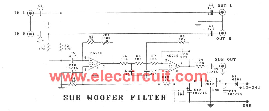
This subwoofer filter set is suitable for use with a high-quality car audio system. The circuit is designed to operate with a 12-volt DC power supply. The subwoofer filter set serves as an essential component in enhancing the audio experience...

LM5576MHX absolute maximum ratings: (1) VIN to GND: 76V; (2) BST to GND: 90V; (3) PRE to GND: 76V; (4) SW to GND (Steady State): -1.5V; (5) BST to VCC: 76V; (6) SD, VCC to GND: 14V; (7) BST...
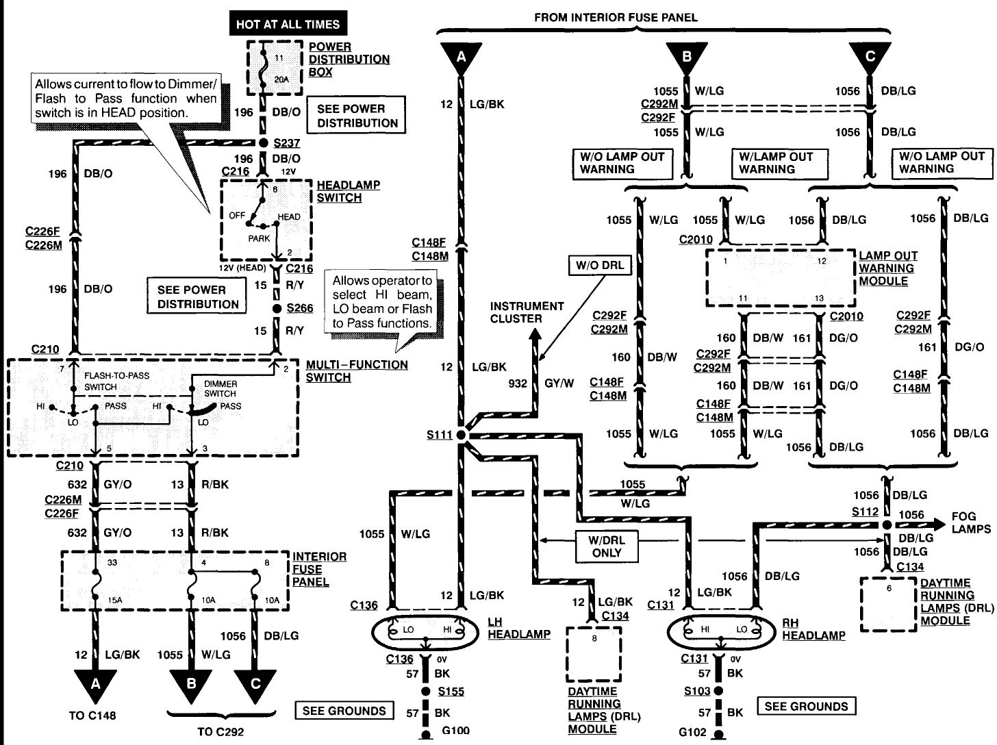
A 1996 Ford Explorer has non-functional headlights. The vehicle has operational low beams and interior lights. The owner has replaced the bulbs, checked the fuses, relays, and light switch, yet the headlights remain inoperative. Suggestions are requested to identify...
NE5532DR absolute maximum ratings: (1) Supply voltage: VCC+ 22 V; VCC-: -22 V; (2) Input voltage, either input VCC ±; (3) Input current: ±10 mA; (4) Duration of output short circuit: Unlimited; (5) Package thermal impedance, JA: D package...
If circuits experience frequency overvoltage conditions, continually replacing blown fuses can become quite costly. This shutdown circuit addresses that issue by substituting the fuse with a relay and a low-current SCR. When the input voltage exceeds the threshold established...