
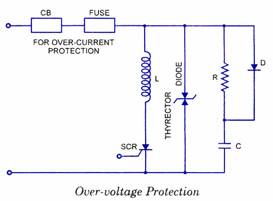
Resettable Shutdown circuits

The shutdown circuit described is an efficient solution for managing overvoltage conditions in electronic circuits. By replacing traditional fuses with a relay and a low-current Silicon Controlled Rectifier (SCR), the design minimizes the cost and inconvenience associated with frequent fuse replacements. The Zener diode (D1) serves as a critical component in this circuit, providing a precise voltage reference that determines the trip point for overvoltage conditions.
When the input voltage rises above this predetermined threshold, the Zener diode conducts, allowing current to flow to the gate of SCR1. This triggers the SCR, which in turn energizes the relay coil. The relay operates by switching its contacts; specifically, it moves from a normally closed position to a normally open position, effectively disconnecting power from the load. This mechanism ensures that the circuit is protected from excessive voltage, thereby preventing potential damage.
To reset the circuit after an overvoltage event, the normally closed pushbutton switch (S1) is employed. Pressing this switch interrupts the power to the relay, allowing its wiper arm to return to the normally closed position. This action restores power to the circuit, enabling it to resume normal operation.
For applications that involve circuits with varying sensitivity to overvoltage, the variable trip-point shutdown circuit variant offers flexibility. This design allows for adjustment of the trip point, accommodating different operational requirements. The adjustment range is designed to provide a 30% variance, ensuring that the circuit can be tailored to specific needs. It is essential to select the Zener diode with a voltage rating that is slightly below the minimum desired threshold to ensure reliable operation and protection.
Overall, this shutdown circuit design is a robust solution for preventing damage from overvoltage conditions, enhancing the reliability and longevity of electronic systems. If your circuits experience frequency overvoltage conditions, continually replacing blown fuses can get pretty expensive. However, this shutdown circuit overcomes that deficiency by replacing the fuse with a relay and a low-current SCR.
When the input voltage rises above the threshold set by the Zener diode (Dl), a current of sufficient magnitude is applied to the gate of SCR1, which turns it on. That draws current through the relay coil and energizes it, which swings its commutator to its normally open contact, and disrupts power to the circuit under power.
Switch SI, a normally closed pushbutton switch, is used to reset the circuit; it does so by interrupting power to the relay. When SI is pressed, the relay`s wiper arm returns to the normally closed position, restoring power to the connected circuit. If you deal with a number of circuits that have different burn-out levels, try the circuit in B. That circuit variation, a variable trip-point shutdown circuit, allows you to adjust the shutdown threshold to whatever level you desire.
The circuit adjustment allows for the 30% variance in the trip point. The zener diode should be selected to have a voltage rating that is slightly lower than the minimum desired threshold voltage. 🔗 External reference
Related Circuits
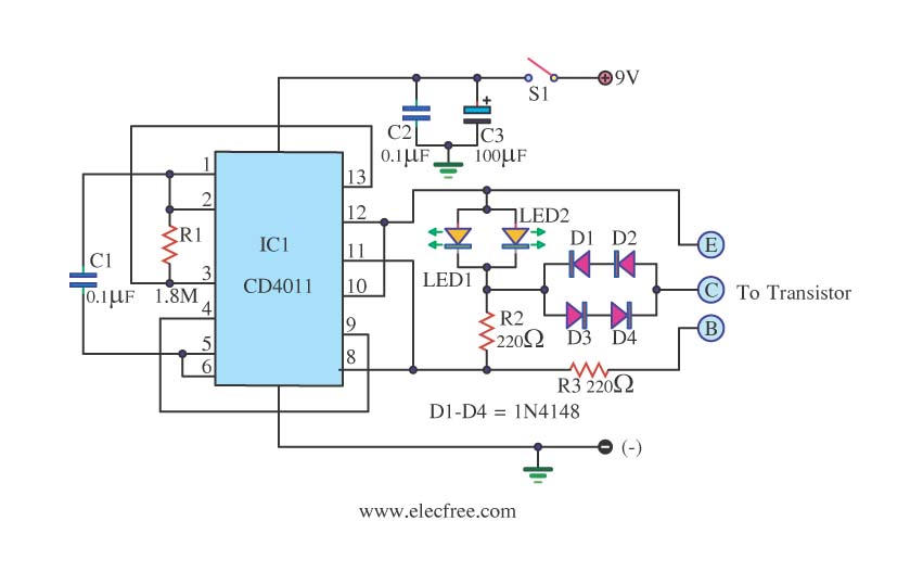
This is a transistor tester integrated into a circuit or printed circuit board (PCB). It is utilized when a project does not function correctly, allowing for the testing of electronic components. The transistor tester is a crucial tool in electronic...

The circuit described is straightforward yet efficient in its operation. The transistor Tr1 is utilized in a grounded base mode, with an input directed to its emitter to facilitate a low impedance input. The circuit is designed to operate effectively...
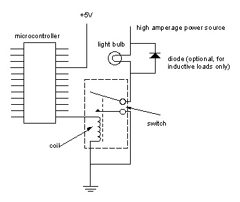
Digital output from a microcontroller is typically a low-amperage signal. For example, when a pin is set HIGH on the microcontroller (in Wiring/Arduino, it is digitalWrite(somePin, HIGH);), the voltage from that pin is usually +3.3V or +5V, with the...
Silicon Controlled Rectifiers (SCRs) are sensitive to high voltage, over-current, and transients. To ensure satisfactory and reliable operation, they must be protected against such abnormal operating conditions. Due to the complexity and cost of protection mechanisms, devices with ratings...
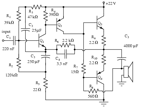
Note that Q3 and Q4 in the figure below are complementary, with Q3 being an NPN transistor and Q4 being a PNP transistor. This circuit is suitable for moderate power audio amplifiers. For a detailed explanation of this circuit,...

The circuit utilizes six 12-volt lead-acid batteries to power the load. Three batteries are connected in series to generate 36 volts, while the other three are connected in parallel to maintain 12 volts. The total discharge current is 30...
Warning: include(partials/cookie-banner.php): Failed to open stream: Permission denied in /var/www/html/nextgr/view-circuit.php on line 713
Warning: include(): Failed opening 'partials/cookie-banner.php' for inclusion (include_path='.:/usr/share/php') in /var/www/html/nextgr/view-circuit.php on line 713