
line follower robot
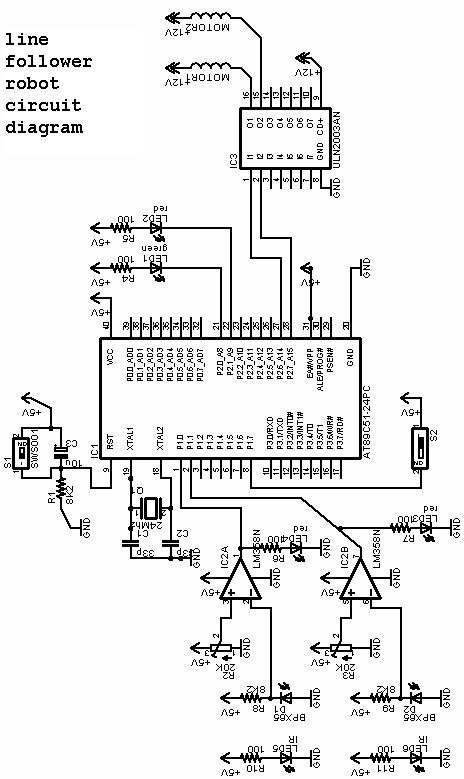
The line follower robot is designed to autonomously navigate along a designated path, typically marked by a contrasting line on the ground. The core of this project is the 8051 microcontroller, which serves as the brain of the robot, processing inputs from various sensors and controlling the motors accordingly.
The circuit diagram includes essential components such as the 8051 microcontroller, infrared (IR) sensors, motor driver circuits, and power supply units. The IR sensors are strategically placed on the robot's underside to detect the line. When the sensors detect the line, they send signals to the microcontroller, which processes this information and determines the appropriate motor actions to keep the robot on track.
The motor driver circuit is crucial for controlling the movement of the robot. It interfaces between the microcontroller and the motors, allowing for bidirectional control of the wheels. This enables the robot to make turns and adjustments as needed to stay aligned with the path.
Power supply considerations are also integral to the design. The circuit typically requires a stable DC power source to ensure reliable operation of the microcontroller and motors. Battery packs are commonly used to provide the necessary voltage and current.
In summary, the line follower robot project using the 8051 microcontroller is a practical application of embedded systems, showcasing the integration of sensors, microcontrollers, and motor control in a compact robotic platform. The project report includes a detailed explanation of the design, implementation, and testing phases, providing valuable insights for enthusiasts and learners in the field of robotics and automation.Line Follower Robot Project Using 8051 with circuit diagram is explained in this abstract. Download line follower or chaser robot full project report 🔗 External reference
Related Circuits
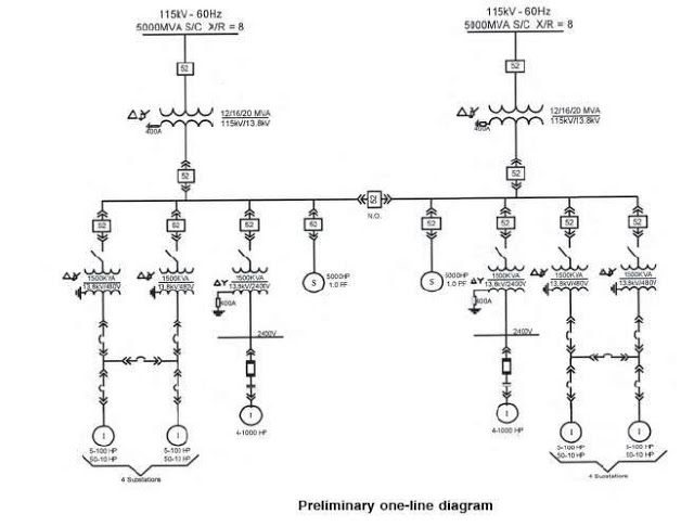
The single line diagram is a circuit diagram where a "one-line" representation illustrates the three phases of a three-phase power system. In addition to displaying the ratings and sizes of electrical equipment and circuit conductors, a well-drawn one-line diagram...
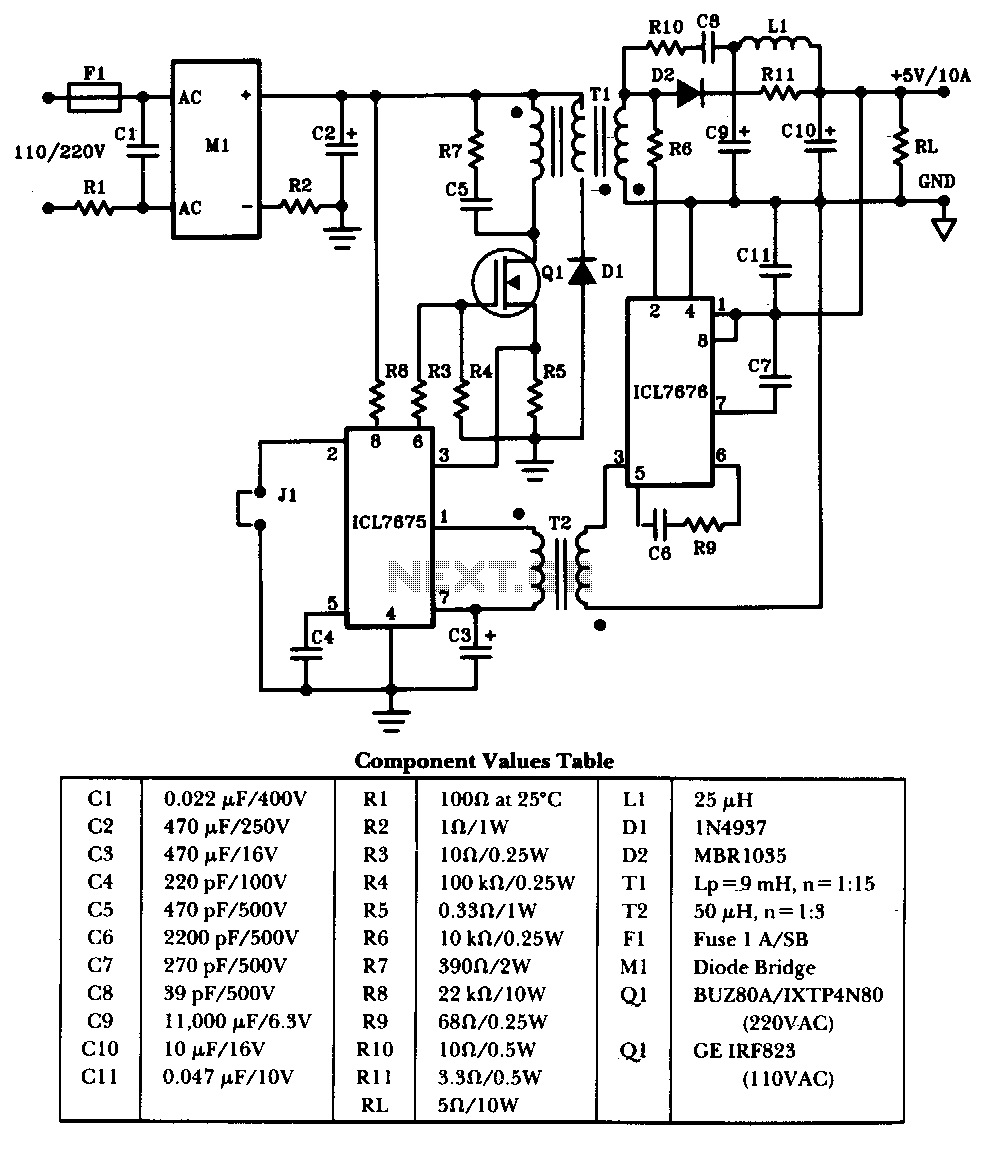
The schematic illustrates a 50W power supply providing a 5V, 10A output. It operates as a flyback converter in continuous mode. The circuit incorporates both primary and secondary side controllers, offering full protection against fault conditions such as overcurrent....
A simple and easy telephone line tester circuit that can be used for testing telephone lines. The telephone line tester circuit is designed to verify the functionality and integrity of telephone lines. It typically comprises a few essential components, including...
The following text describes construction, testing and use of an electronic telephone line simulator of my own design. This self-build project can simulate a telephone call / connection between any two local telephone devices. This for a fraction of...
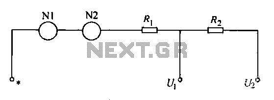
A voltmeter operates through a measuring mechanism in a specified circuit, utilizing a moving coil in series with additional resistance. The fixed coil is denoted as N1, while the moving coil is designated as N2. The additional resistances are...
This project is used as an electronic private exchange. It has two telephones, which have the intercom facility, and they can be connected to the telephone line. All the functions are controlled by the 8-bit microcontroller AT89C2051 which has...
Warning: include(partials/cookie-banner.php): Failed to open stream: Permission denied in /var/www/html/nextgr/view-circuit.php on line 713
Warning: include(): Failed opening 'partials/cookie-banner.php' for inclusion (include_path='.:/usr/share/php') in /var/www/html/nextgr/view-circuit.php on line 713