
Electrical Single Line Diagram - Part Two
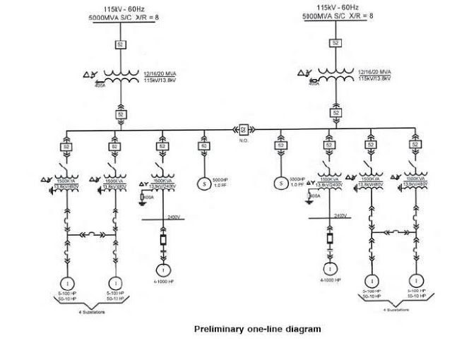
The single line diagram is a vital tool in electrical engineering, providing a clear and concise representation of complex power systems. By condensing multiple phases into a single line, it simplifies the analysis and understanding of the system's operation. Each component is represented with standardized symbols, which enhances communication among engineers, technicians, and maintenance personnel. The arrangement of components by voltage levels not only aids in visual clarity but also assists in troubleshooting and maintenance tasks.
Power flow tracing is a critical function of the single line diagram, allowing engineers to identify the path of current from the source to various loads. This capability is essential for maintenance activities, ensuring that technicians can safely isolate components without disrupting the entire system. Furthermore, the inclusion of ratings, such as voltage and current capacities, provides essential information for ensuring that equipment operates within safe limits.
The diagram's role in safety is paramount; it serves as a reference for compliance with industry standards and regulations. By identifying potential problem areas, it allows for proactive measures to be taken, thereby reducing the likelihood of failures and enhancing operational safety. The detailed documentation of circuit conductors and protective devices ensures that the system is designed and maintained according to best practices, minimizing risks associated with electrical hazards.
In summary, the single line diagram is an indispensable resource in the design, operation, and maintenance of electrical power systems. Its ability to convey complex information in a simplified format supports effective communication and enhances the overall safety and reliability of electrical installations.The single line diagram is circuit diagram where "one-line" is shown to represent three phases of a three phase power system. In addition to showing the ratings and size of electrical equipment and circuit conductors, a properly drawn one-line diagram will also show an electrically correct distribution of power with respect to current flow from th
e power source to the downstream loads or panelboards. Inaccuracy in this documentation and failure to update one-line diagrams on a regular basis as electrical systems invariably grow over time often results in increased down time when system failures occur, The single line diagram offers several benefits to the facility it outlines, especially: identification of possible problem places, improved safety conformity, and enhanced staff safety. Single-line diagram is a simplified notation for representing a three-phase power system; Instead of representing each of three phases with a separate line or terminal, only one conductor is represented.
On one-line power diagrams, components are usually arranged in order of decreasing voltage levels. The highest voltage component is shown at the top right of the drawing. In order to find out how power is supplied to a component, start at the component and trace the flow of power backwards through the drawing. This method will be most useful in locating the correct circuit breaker to isolate a component for maintenance The voltage, phase, and frequency of incoming and outgoing circuits.
The available short circuit and ground currents of the power company system, and type of ground used. The abbreviations used for principal meters, instruments, and other devices (not including relaying, which is listed in Fig.
2) are listed in fig. 1 above. Each device in an automatic switching equipment has a device function number (see fig. 2) which is placed adjacent to or within the device symbol on all wiring diagrams and arrangement drawings so that its function and operation may be readily identified. Compare the calculated 1-1/2 to 4-cycle (interrupting) current duty with the circuit breaker symmetrical interrupting capability.
(as per ANSI C37. 010: Application Guide for AC High-Voltage Circuit Breakers Rated on a Symmetrical Current Basis). Compare the feeder cable short-circuit heating limit with the maximum available short circuit current time Kt times Ko. (See IEEE 242-1975: IEEE Recommended Practice for Protection and Coordination of Industrial and Commercial Power Systems).
the calculations performed in accordance with Reference to (ANSI C37. 010: Application Guide for AC High-Voltage Circuit Breakers Rated on a Symmetrical Current Basis) determine only medium and high-voltage circuit breaker ratings. Perform short-circuit studies to determine relay operating currents in accordance with procedures outlined in IEEE 357-1973: IEEE Guide for Protective Relaying of Utility-Consumer Interconnections).
Show ratings selected for external devices, such as grounding resistors, control power transformers, considering the type of protective relaying instrumentation and metering required. Confirm the selection of relay ratings and characteristics by performing a complete system short-circuit and coordination study.
As per the following IEEE Standards: Verify that all circuit conductors are applied within the conductor short-circuit heating limit. (As per IEEE 242-1975: IEEE Recommended Practice for Protection and Coordination of Industrial and Commercial Power Systems.
) 🔗 External reference
Related Circuits
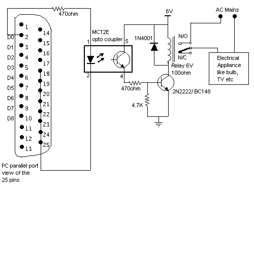
Here is a circuit for using the printer port of a PC, for control application using software and some interface hardware. The interface circuit along with the given software can be used with the printer port of any PC...
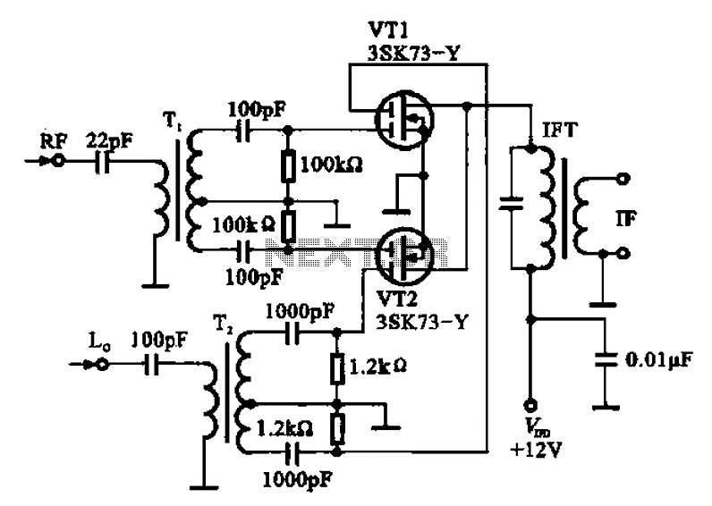
A balanced mixer circuit is illustrated using two dual-gate field effect transistors (FETs). The RF signal is coupled to the gates of these transistors through an input signal transformer (T1). Additionally, a local oscillation signal is introduced to the...
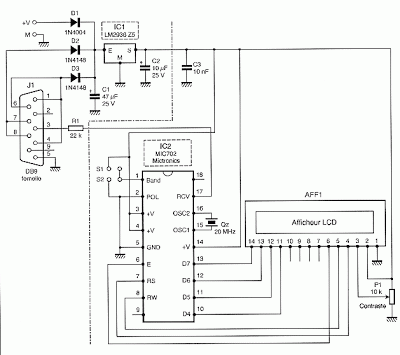
To convert a standard LCD interface from parallel to a serial interface model, a microcontroller or a dedicated circuit such as the MIC 702 from Mictronics can be used. This circuit is specifically designed to transform the parallel interface...
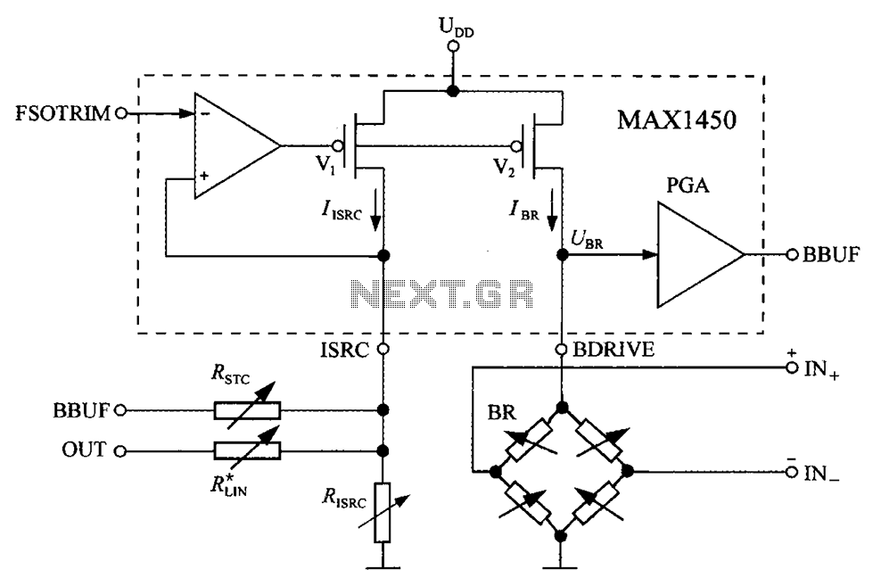
The circuit diagram for the bridge integrated pressure signal conditioner MAX1450 is composed of various components. The MAX1450 is a high-performance integrated circuit designed for signal conditioning in pressure sensing applications. It is particularly suited for use with resistive bridge...
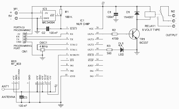
In this project, we will see how to build a single-channel remote control. It is an easy project to do: by using a pre-assembled radio module, we will get a compact card without sacrificing major performance. The insert function...
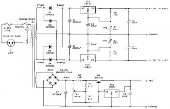
This bench power supply features three solid-state DC power supplies. The first supply provides an output of 1.5 to 15 volts at 1 ampere. The second supply offers a range of -1.5 to -15 volts at 1 ampere. The...