
Line Follower Sensor
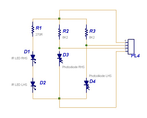
The Line Follower Sensor Circuit is designed to detect the presence of a line, typically a black line on a white surface, allowing a robot or vehicle to follow the path. The core components of this circuit include two Infrared LEDs (D1 and D2) and phototransistors or photodiodes that act as sensors.
When the Infrared LEDs emit light, it reflects off the surface beneath them. If the surface is light-colored (like white), the light is reflected back to the phototransistors, which will not trigger the sensors. Conversely, if the surface is dark (like black), less infrared light is reflected, leading to a different response from the sensors. This contrast allows the circuit to determine the position of the line.
The circuit typically includes a microcontroller or an operational amplifier to process the signals received from the phototransistors. Based on the input from the sensors, the microcontroller can adjust the motion of the motors controlling the wheels of the robot, ensuring that it stays on the designated path.
Powering the circuit can be achieved using a battery or a power supply, ensuring that the LEDs and sensors receive the necessary voltage and current for operation. The simplicity of this circuit makes it an excellent choice for educational purposes, as well as for hobbyists interested in robotics.
Overall, the Line Follower Sensor Circuit exemplifies a fundamental application of infrared technology in automation and robotics, demonstrating how basic electronic components can be used to create intelligent behavior in machines.The following circuit shows about Line Follower Sensor Circuit Diagram. Features:Simple circuit, Infra-Red LEDs D1 and D2 will emit Infra-Red .. 🔗 External reference
Related Circuits
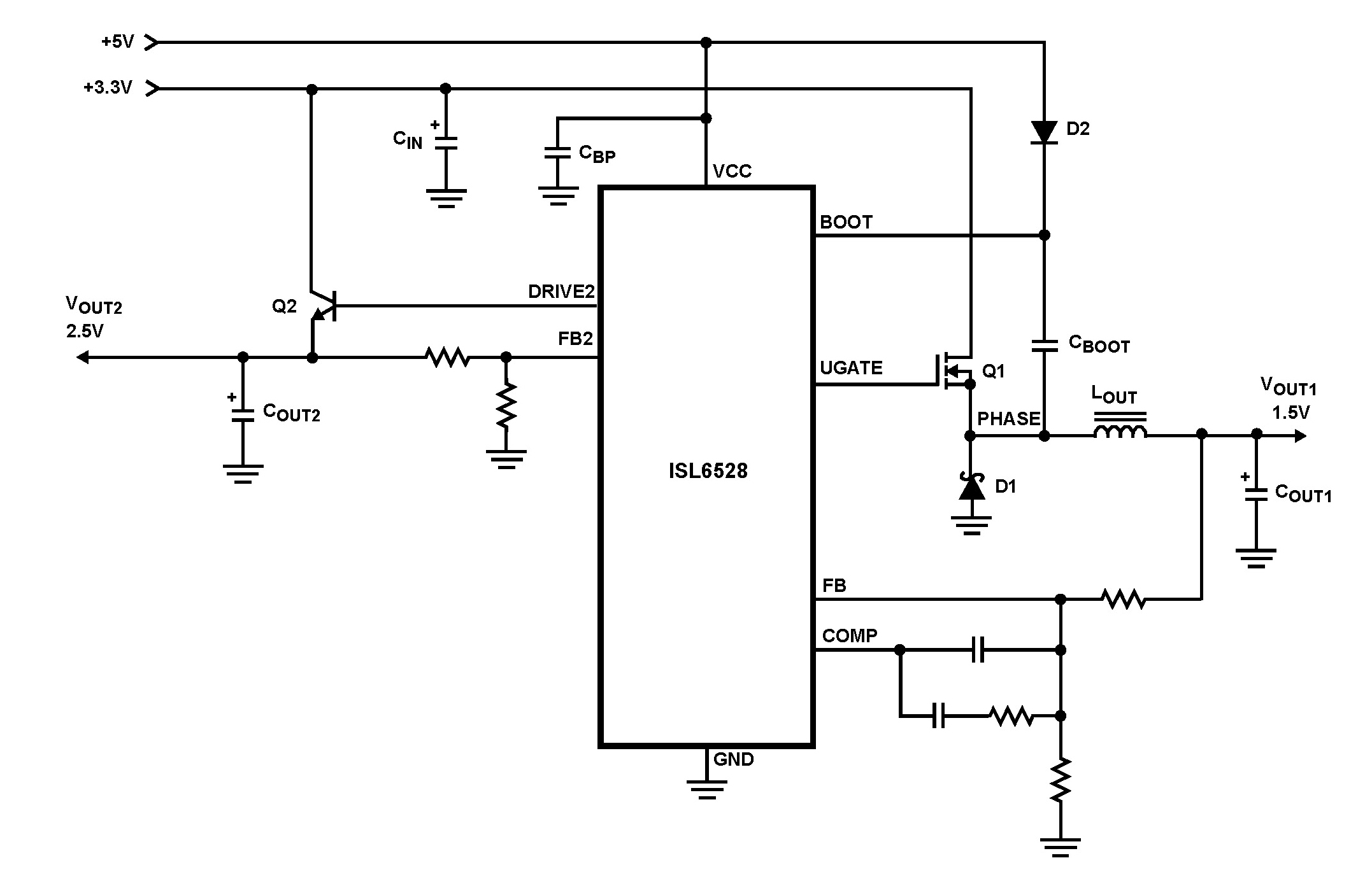
The ISL6528 offers power control and protection for two output voltages in high-performance graphics cards and other embedded processor applications. This dual-output controller drives an N-Channel MOSFET in a standard buck topology and an NPN pass transistor in a...
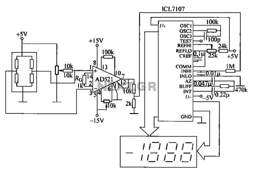
A pressure sensor circuit features a pressure sensor with a nominal resistance of 120 ohms. The amplifier circuit utilizes an AD521 operational amplifier with a gain of 100. It includes resistor components Rs and Rc, along with a decision-making...
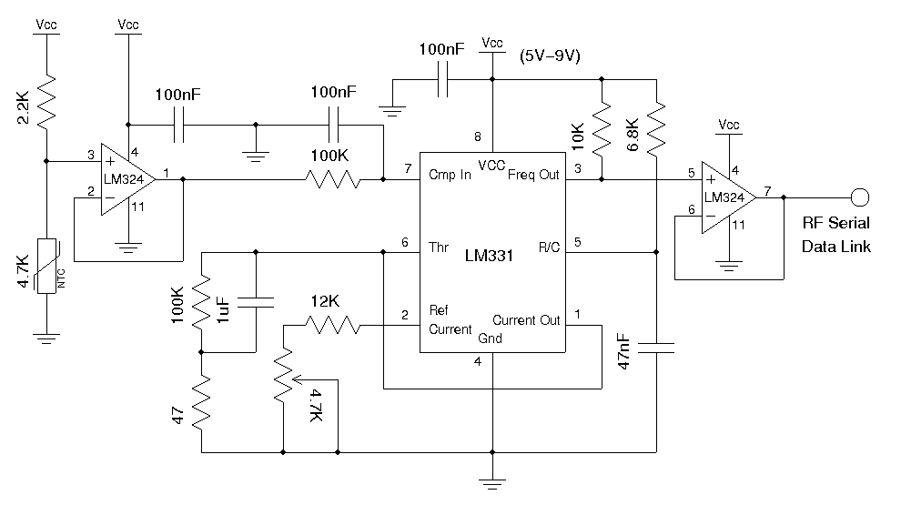
A wireless temperature sensor allows temperature measurements to be taken anywhere within the range of the transmitter and receiver. One straightforward approach to achieve this is by utilizing a voltage-to-frequency conversion chip in conjunction with an analog temperature sensor,...
A long time ago, when telephones were simple and reliable from an electrical standpoint, telecom operators installed surge protection on all telephone lines exposed to storm risks. Paradoxically, with the advent of delicate and expensive equipment such as electronic...
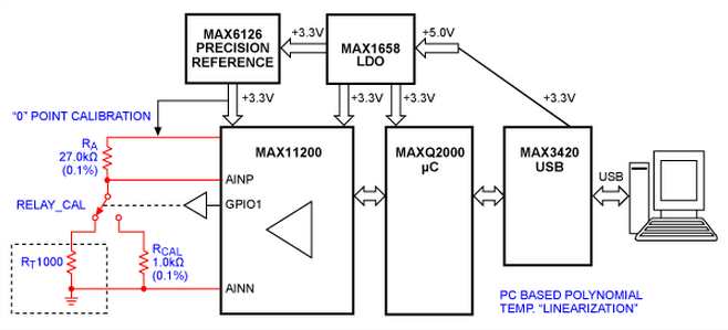
This article explains how platinum resistance temperature detectors (PRTDs) can perform measurements over wide temperature ranges of -200 °C to +850 °C, with absolute accuracy and repeatability better than ±0.3 °C, when used with modern processors capable of resolving...
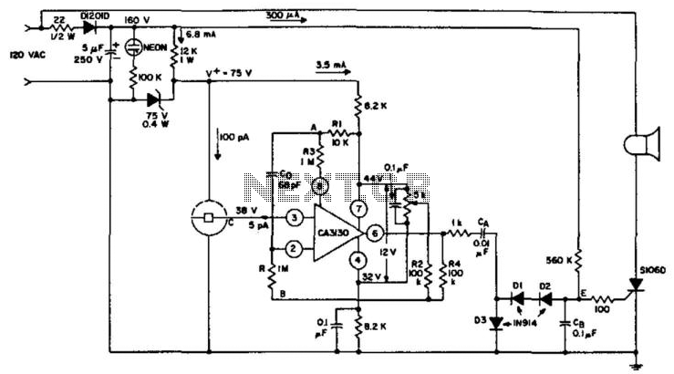
An ionization chamber in conjunction with a high-impedance CA3130 operational amplifier is utilized to detect the presence of smoke. When smoke is detected, the CA3130 ceases oscillation, which in turn triggers the S106D silicon-controlled rectifier (SCR) to sound an...
Warning: include(partials/cookie-banner.php): Failed to open stream: Permission denied in /var/www/html/nextgr/view-circuit.php on line 713
Warning: include(): Failed opening 'partials/cookie-banner.php' for inclusion (include_path='.:/usr/share/php') in /var/www/html/nextgr/view-circuit.php on line 713