
Line-Operated Smoke Detector

The circuit employs an ionization chamber, which consists of two electrodes separated by a gas-filled space. When smoke particles enter the chamber, they disrupt the ionization process, leading to a decrease in ion current. This change in current is monitored by the CA3130 op-amp configured in an oscillator setup. The high-impedance nature of the CA3130 allows it to detect minute changes in the ion current caused by the presence of smoke.
In normal conditions, the CA3130 maintains a stable oscillation frequency. However, when smoke is detected, the ionization chamber's current drops, causing the CA3130 to stop oscillating. This cessation of oscillation serves as a signal that activates the S106D SCR. The SCR is a type of semiconductor device that can switch on and off based on the control signal it receives. Once triggered, the S106D SCR completes the circuit to the alarm system, which could be a sound-producing device such as a buzzer or siren, alerting occupants to the presence of smoke.
The overall design of this smoke detection system is efficient and reliable, leveraging the high sensitivity of the ionization chamber and the responsive characteristics of the CA3130 and S106D SCR. This configuration ensures timely detection of smoke, providing an essential safety feature in residential and commercial environments. Proper implementation of this circuit requires careful consideration of component values, power supply requirements, and alarm output specifications to ensure effective operation. Using an ionization chamber and a high-impedance (CA3130) op amp, the presence of smoke will cause the CA3130 to stop oscillating, triggering S106D SCR, sounding the alarm.
Related Circuits

This lie detector circuit diagram provides two readings: one for challenging questions directed at the subject and another to display the subject's emotional state in general. The emotional states are detected not only by heart rate variations and perspiration...
This project outlines a simple water detector circuit. The components required for this project include the following: 1. One IC 555 timer, and 2. A small-sized general-purpose relay. The water detector circuit utilizes the IC 555 timer configured in a...
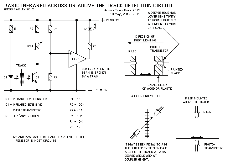
This page presents information on infrared - Across The Track train detection circuits. The circuits are designed around the LM339 comparator chip and can use a wide assortment of matched infrared - emitter / detector pairs. The basic circuit...
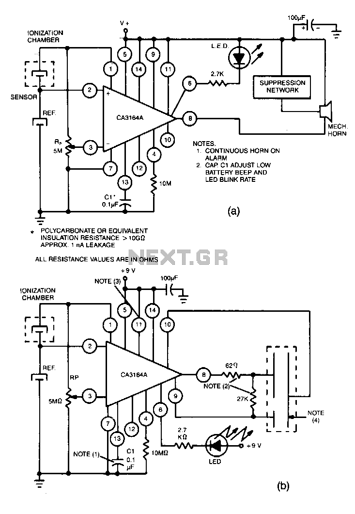
Utilize the CA3164A BiMOS detector/alarm system for operation as a smoke detector with an electromechanical horn (refer to Fig. 40-la). The output driver at terminal 8 is employed, utilizing a large npn transistor Q3 with an active pull-up, while...

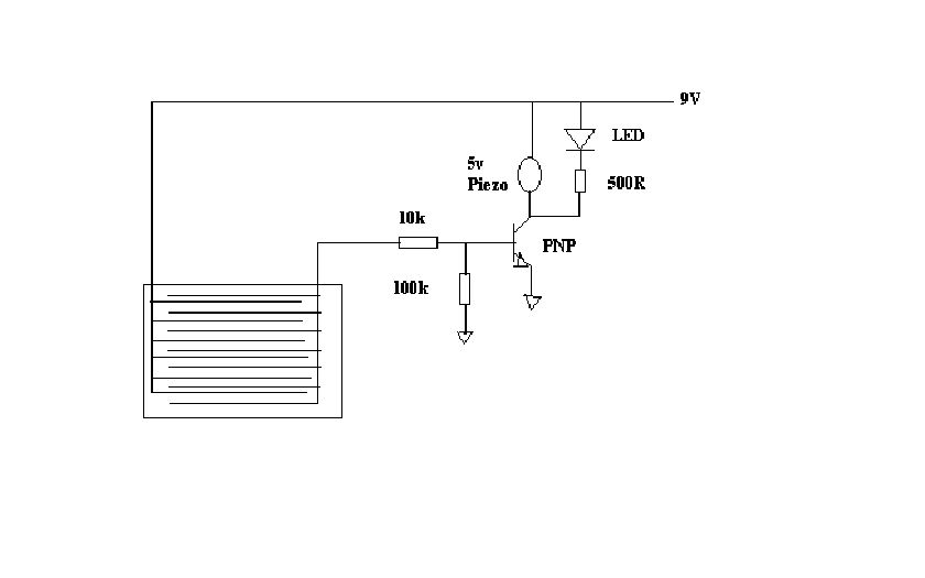
This circuit employs a 1458 dual op-amp to create a radar detector. C1 acts as the radar signal detector. The first op-amp functions as a current-to-voltage converter, while the second op-amp buffers the output to drive the piezo transducer....
This simple circuit can detect the invisible fields of voltage which surround all electrified objects. It acts as an electronic "electroscope." Regular foil-leaf electroscopes deal with electrostatic potentials in the range of many hundreds or thousands of volts. The...