
Line Following Robot Sensor
The line-following robot sensor circuit employs a straightforward design that integrates essential components for effective operation. The CNY70 opto-sensor serves as the core of the system, combining an infrared LED and a phototransistor in a single package. This integration simplifies the layout and reduces the number of external components required.
The infrared LED emits light that is reflected by the surface beneath the robot. The phototransistor detects the intensity of the reflected light, which varies based on the color of the surface—black surfaces absorb more light, while white surfaces reflect more. This principle is leveraged to create a feedback mechanism that enables the robot to follow the designated path.
The calibration procedure is crucial for the optimal functioning of the sensor. Adjusting potentiometer P1 allows for fine-tuning the sensitivity of the system, ensuring that the robot can differentiate between the black and white surfaces under varying ambient light conditions. The use of resistor R2 and the transistor T1 in the circuit creates a threshold that determines when the LED indicator (D1) is activated.
In applications where the robot needs to respond to the detected signals, the addition of a reed relay in parallel with the visual indicator allows for physical control of the robot's movement. This relay can be employed to engage motors or other actuators, facilitating actions such as stopping or redirecting the robot based on the sensor's readings.
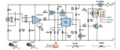
Furthermore, the transition at the collector of T2 provides a digital signal that can interface with microcontrollers or other logic circuits, enabling more complex behaviors and decision-making processes in the robot's operation. The overall design emphasizes simplicity and effectiveness, making it suitable for educational purposes and basic robotics projects.This Line Following Robot sensor or surface scanner for robots is a very simple, stamp-sized, short range (5-10mm) Infrared proximity detector wired around a standard reflective opto-sensor CNY70(IC1). In some disciplines, a line following robot or an electronic toy vehicle go along a predrawn black line on a white surface.
In such devices, a surf ace scanner, pointed at the surface is used to align the right track. IC1 contains an infrared LED and a phototransistor. The LED emit invisible infrared light on the track and the phototransistor works as a receiver. Usually, black colored surface reflects less light than white surface and more current will flow through the phototransistor when it is above a white surface. When a reflection is detected (IR light falls on the phototransistor) a current flows through R2 to ground which generates a voltage drop at the base of T1 to make it conduct.
As a result, transistor T2 start conducting and the visual indicator LED(D1) lights up. Capacitor C2 works as a mini buffer. After construction and installation, the scanner needs to be calibrated. Initially set P1 to its mechanical centre position and place the robot above the white portion of the track. Now slowly turn P1 to get a good response from D1. After this, fine tune P1 to reduce false detection caused by external light sources. Also ensure that the LED remains in off condition when the sensor module is on the blackarea. Repeat the process until the correct calibration is achieved. The red color LED (D1) is only a visual indicator. You can add a suitable (5V) reed relay in parallel with D1-R4 wiring after suitable alterations to brake/stop/redirect the robot.
Similarly, the High to low (H-L) transition at the collector of T2 can be used as a signal to control the logic blocks of the robot. Resistor R1 determines the operating current of the IRLED inside IC1. The sensing ability largely depends on the reflective properties of the markings on the track and the strength of the light output from IC1.
🔗 External reference
Related Circuits
A PIR sensor is triggered when using a timer to wait for 2 seconds after the sensor is activated. Without the timer, the sensor operates as intended. The PIR sensor is connected to an ATMega328p microcontroller, which has three...
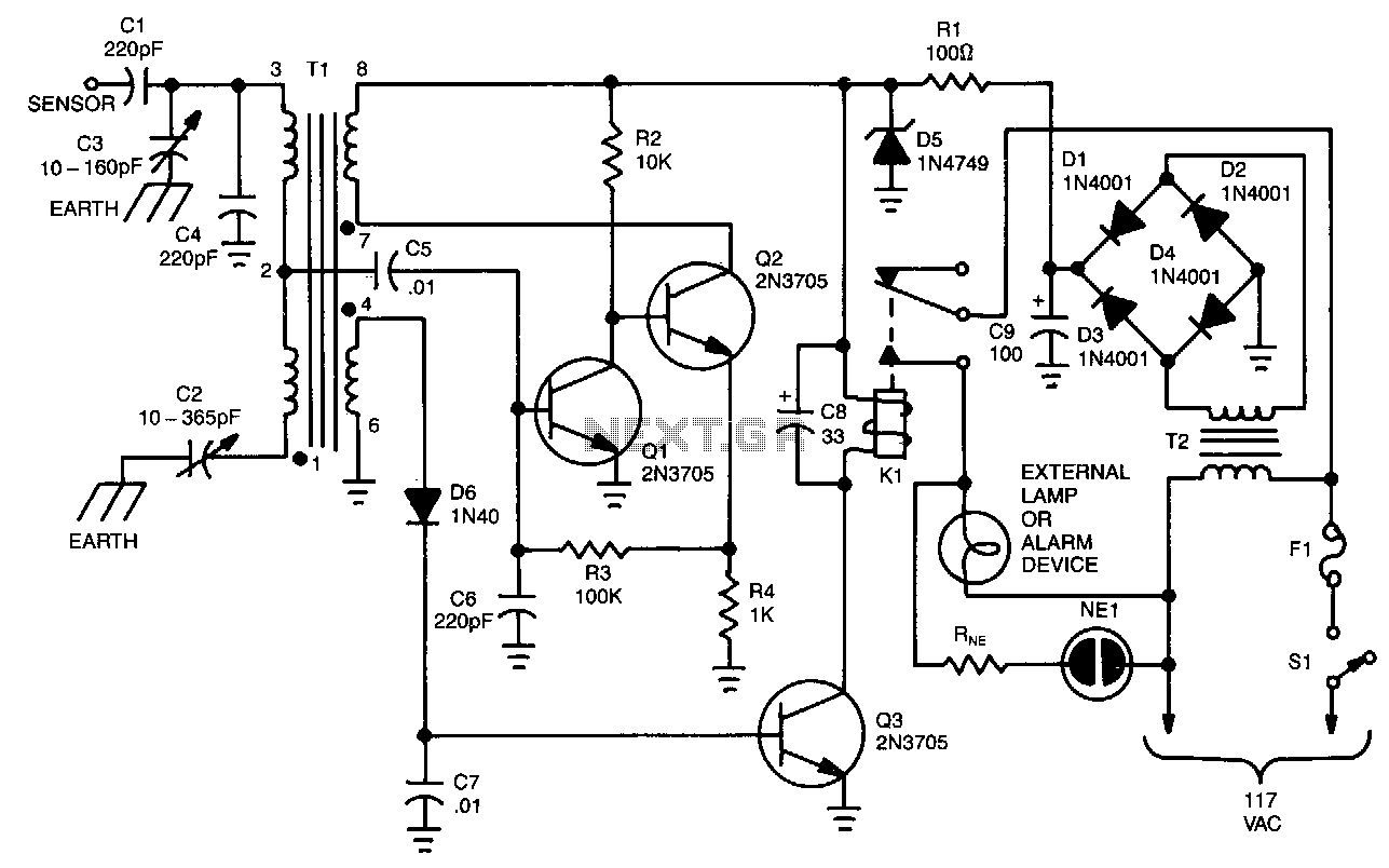
The unit is built around a balanced-bridge circuit that utilizes both capacitance and inductance. The bridge comprises capacitors C2 and C3, along with the center-tapped winding of transformer Tl. One end of the bridge is connected to ground through...
The use of diode rectifiers in AC voltmeters with a low lower limit of measurement range (0.5-1 V) leads to significant nonlinearity of the scale due to the nonlinearity of the current-voltage characteristics of diodes. The incorporation of electronic...
This Super Light Sensor responds to minute fluctuations in light levels, automatically adjusting from approximately 200 lux to 60,000 lux (from a modestly lit room to direct sunlight). It has various potential applications, such as detecting a car entering...
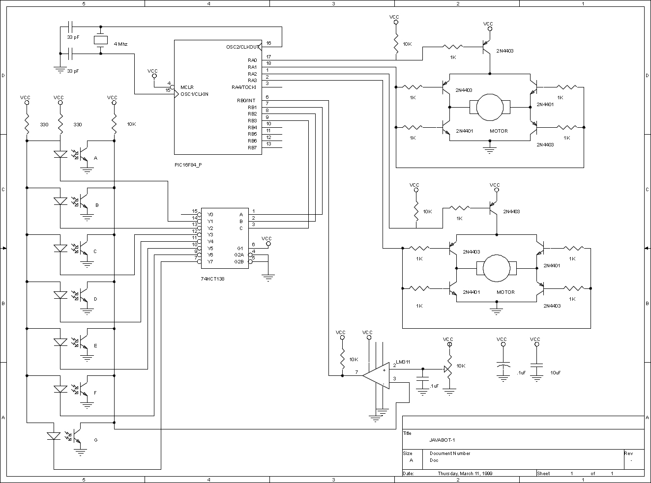
The JavaBot1 is a compact line-following robot engineered to trace a black line drawn on a dry erase board. It is specifically designed to navigate along very narrow curves. The JavaBot1 employs a differential drive mechanism, which allows it to...
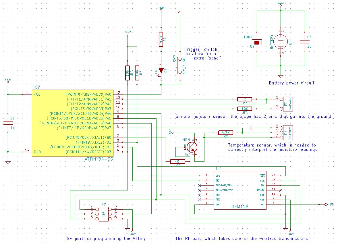
The goal is to create a final package that is as inconspicuous as possible, without any visible wires or adapters. This necessitates powering the project with a small battery. To conserve energy, the ATMega (or potentially the ATTiny) will...