
microcontroller PIR sensor triggered by itself when using timer works without timer
The circuit design involves integrating a Passive Infrared (PIR) sensor with an ATMega328p microcontroller for motion detection applications. The PIR sensor operates by detecting infrared radiation emitted by objects in its field of view, making it suitable for applications such as security systems and automated lighting controls. The sensor features three essential pins: VCC for power supply, GND for ground connection, and AL (Alarm) output, which indicates motion detection through an open collector configuration.
In this implementation, the AL output pin is connected to the PC0 pin of the ATMega328p, which is configured as an input with an internal pull-up resistor. This configuration ensures that the microcontroller reads a HIGH signal when no motion is detected and transitions to LOW when motion is detected. An LED is connected to the PC5 pin, which serves as a visual indicator of motion detection. The microcontroller's firmware includes a state management system that utilizes a volatile boolean variable `motion_detected` to track whether motion has been detected.
The core functionality is driven by two primary functions: `check_sensor()` and `check_timer()`. The `check_sensor()` function evaluates the state of the AL pin. If the pin is LOW, indicating motion, the LED connected to PC5 is turned ON. If motion is detected and the `motion_detected` flag is not set, the system triggers a brief LED blink and sets the `motion_detected` flag to TRUE, initiating a 2-second countdown. The `check_timer()` function monitors the timer count; once the timer reaches the designated interval, it resets the `motion_detected` flag, allowing for new motion signals to be processed.
The timer is configured using the ATMega328p's Timer/Counter 1 (TC1) with a prescaler of 256, resulting in a timer increment rate of approximately 3906 increments per second, derived from the microcontroller's clock frequency. This precise timing mechanism ensures that the system can accurately ignore motion signals for the specified duration.
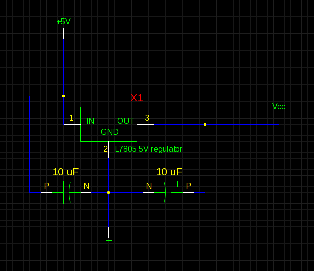
The power supply design employs a stabilized DC source, providing approximately 6.5V to the circuit. This voltage is regulated down to the required 5V for the microcontroller and PIR sensor. The schematic representation includes connections for the microcontroller's power, ground, and input/output pins, although it omits some programming interface connections for clarity.
In summary, the circuit effectively integrates a PIR sensor with a microcontroller to create an efficient motion detection system. The implemented timer logic prevents false triggers by managing the motion detection state, while the visual feedback provided by the LED enhances user interaction.A PIR sensor is triggered by itself when using a timer to wait 2 seconds after the sensor is triggered. Without using the timer to wait the sensor works as expected. I have a PIR sensor connected to an ATMega328p. The PIR sensor has three pins; VCC, GND and AL. The AL pin uses open collector to show that motion is detected. What I have done is th at I connected the AL pin to PC0 pin on my ATMega and set up the pin as input with internal pull up resistor and a LED connected to PC5 to show when motion is detected: Everything works as expected, the LED lights up when I wave my hand infront of the sensor and it does not trigger without motion. The sensor sets the AL pin LOW for about 100 - 200 ms. The thing is that I don`t want to use the signal for 2 seconds after motion has been detected. So I implemented a timer and flag logic that ignores the signal during these 2 seconds. The problem is that now the LED lights up by itself after the timer has stop counting and start accepting motion signals volatile bool motion_detected; void setup_default_values() { DDRC |= (1 << PC5); DDRC |= (1 << PC4); DDRC |= (1 << PC3); DDRC &= ~(1 << PC0); PORTC |= (1 << PC0); TCCR1B |= (1 << CS12); // Timer 1B set up to use a prescaler of 256 TCNT1 = 0; // Timer value set to 0 motion_detected = false; } void check_sensor() { if (PINC & (1 << PC0) { PORTC &= ~(1 << PC5); }else{ PORTC |= (1 << PC5); if (!motion_detected) { PORTC |= (1 << PC3); _delay_ms(50); PORTC &= ~(1 << PC3); PORTC |= (1 << PC4); TCNT1 = 0; motion_detected = true; } } } #define F_CPU 1000000UL /* * Timer increments per second * * This value represents how many increments the timer will do to the TCNT1 register * per second.
* * To produce this value you divide the clock frequency in hz with the prescaler amount. * For example: * 1000000 / 256 = 3906 */ #define TMR_INC_PER_SEC 3906 void check_timer() { if (!motion_detected) return; if (TCNT1 >= TMR_INC_PER_SEC * 3) { PORTC &= ~(1 << PC4); motion_detected = false; } } int main() { setup_default_values(); blink(4); for (;) { check_timer(); check_sensor(); } return 0; } This function should be ignored unless there is a motion detected. When countdown has been completed timer indicating LED is turned off and motion flag is reset which indicates that a new signal can be accepted.
I have tried adding software debounce functionality where motion is only accepted if PC0 is LOW for a defined amount of cycles. This did not change the faulty behavior. Here is the schematics for the power supply. The circuit is connected to a Stabilized DC power supply where the +5V rail is actually around +6. 5V (I don`t know how to edit the text of a component in gschem). VCC is what I connect to my microcontroller and PIR-sensor, as you will see in the second schematic. Here is the schematics for the microcontroller, the LEDs and the PIR-sensor. Some pins are not shown in the schematics: RESET pin is connected to my programmer, same with MOSI, MISO and SCK.
🔗 External reference
Related Circuits
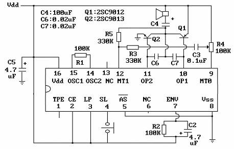
The core component of this circuit is the UM3481 integrated circuit (IC), which operates with a 1.5-volt battery. It is suitable for applications such as electronic doorbells, toys, melody clocks, and music boxes. The UM3481 is engineered to play...
This application note outlines the functionality of the MAX4929E, which manages the switching of all low-frequency signals (LoF) required for a 2:1 HDMI/DVI switch while providing high-level ESD protection for all external lines. It also details how the MAX4929E...
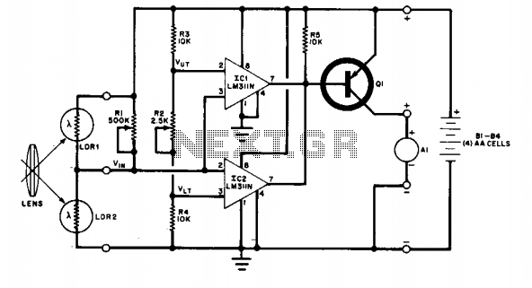
The change in ambient light triggers the alarm by changing the resistance of LDR1 and LDR2. The circuit utilizes two light-dependent resistors (LDR1 and LDR2) to detect variations in ambient light levels. LDRs are passive components that exhibit a change...
Ions are defined as electrically charged atoms. Positively charged ions have a deficiency of electrons, and negatively charged ions have a surplus of electrons. An ion can also be classified as an atom or molecule with an electrostatic charge....

R1 is a 15k ohm resistor. An NTC thermistor rated at 10k ohm, available at Radio Shack in the United States, is utilized. P1 is a 10k ohm potentiometer that sets the low speed (voltage) of the fans at...
This circuit illustrates a flip-flop timer circuit diagram utilizing the 4017 integrated circuit (IC). The key feature includes a push-button switch (S1) that discharges capacitor (C1) through resistor (R2). The 4017 decade counter IC is commonly used in timer and...