
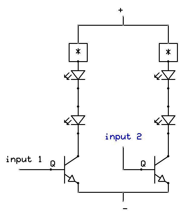
line powered white leds
The described LED circuit operates by connecting multiple white LEDs in series, which allows for a uniform distribution of voltage across each LED. The series connection ensures that the same current flows through all the LEDs, which is crucial for maintaining consistent brightness. When interfacing with a 120VAC power source, it is essential to incorporate a current-limiting resistor to prevent excessive current from damaging the LEDs.
To calculate the required resistance, one must consider the forward voltage drop of each LED, which typically ranges from 2.8V to 3.6V for white LEDs. The total forward voltage drop for 25 LEDs in series would be approximately 70V to 90V. Given the 120VAC supply, the peak voltage (approximately 170V) must also be accounted for, as the LEDs will only conduct during the positive half-cycle of the AC waveform.
The current-limiting resistor can be calculated using Ohm's Law (V = IR). The voltage across the resistor can be determined by subtracting the total forward voltage drop of the LEDs from the peak supply voltage. The formula for the resistor value (R) can be expressed as:
R = (V_peak - V_LED_total) / I
Where:
- V_peak = 170V (peak voltage of the 120VAC supply)
- V_LED_total = Total forward voltage drop of the LEDs (e.g., 75V for 25 LEDs at 3V each)
- I = Desired current through the LEDs, typically in the range of 20mA to 30mA for standard LEDs.
It is important to ensure that the resistor can handle the power dissipation, which can be calculated using P = I²R. Additionally, safety precautions should be taken when working with high-voltage AC circuits, including proper insulation and the use of components rated for the voltage and current levels in the circuit.
This LED circuit design can be adapted for different configurations by altering the number of LEDs and adjusting the resistor value accordingly, ensuring optimal performance and longevity of the LED components.The LED circuit below is an example of using 25 white LEDs in series connected to the 120VAC line. It can be modified for more or less LEDs by adjusting the resistor value. The exact resistance will depend on the particular LEDs used. But working out the resistor value is a bit complicated since current will not continously flow through the resistor.. 🔗 External reference
Related Circuits
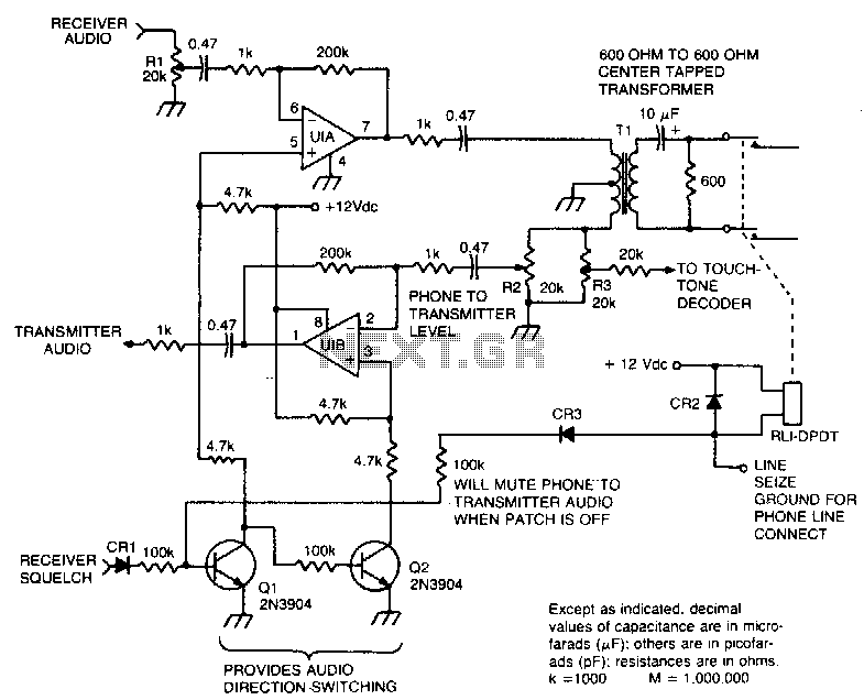
This circuit facilitates the communication link between the receiver and the phone line, as well as the phone line and the transmitter, utilizing an operational amplifier (op-amp) for signal amplification. The described circuit connects a receiver to a phone line...
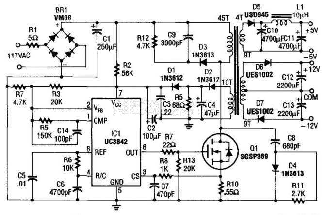
This power supply utilizes an SGS-Thomson UC3842 integrated circuit in an off-line flyback regulator configuration, delivering +5 V at 4 A and ±12 V at 300 mA. This design allows for the use of a compact high-frequency (50 kHz)...
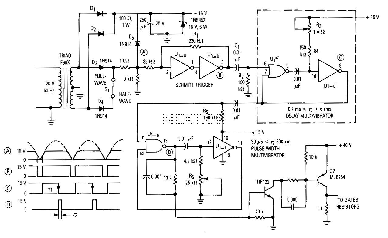
The gate drive that phase controls the four parallel SCRs is achieved using a complementary MOS hex gate MC14572 and two bipolar transistors. This adjustable line-synchronized driver allows SCR conduction from near zero to 180 degrees. A Schmitt trigger...
This is a straightforward project suitable for individuals with basic electronic skills. Connecting this circuit to an audio source will cause the LEDs to blink in sync with the rhythm. The described project is an audio-activated LED circuit that visually...
This very simple and self-powered device was conceived to allow a person to monitor if someone has rung his home door-bell when he was out. As most door-bells use 12Vac supply, the circuit must be simply connected to the...
After constructing numerous Nixie Tube Clocks based on online designs, a personal design was developed. This clock utilizes IN-12 Nixie Tubes and an 8-core Propeller Microcontroller. Although the Propeller may be more powerful than necessary for this task, it...