
Propeller-powered IN-12 Nixie Clock
The circuit design of this Nixie Tube Clock incorporates several key components and configurations that facilitate its operation and functionality. The IN-12 Nixie Tubes serve as the primary display elements, offering a visually appealing method of time representation. Each tube is driven by K155D drivers, which efficiently manage the cathode control through a BCD input, allowing for the display of decimal numbers from 0 to 9. The multiplexing technique employed ensures that only one tube is illuminated at any given time, which not only conserves power but also enhances the longevity of the tubes.
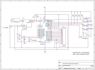
The power supply system is crucial for maintaining stable operation. The TL494-based switching power supply is designed to provide a reliable 5V output for the Nixie drivers and a regulated 3.3V supply for the microcontroller and peripheral components. This dual-regulator setup guarantees that each component receives the appropriate voltage, thereby optimizing performance and preventing damage.
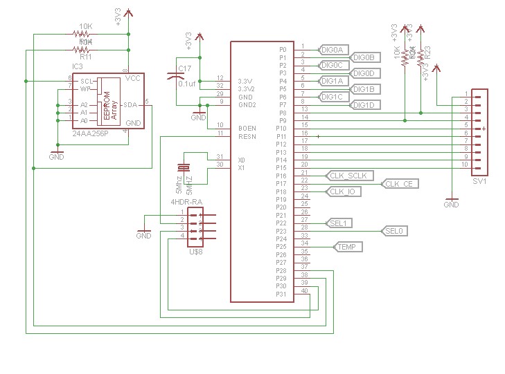
The microcontroller's architecture, centered around the Propeller Microcontroller, allows for flexible programming and expansion. The inclusion of an external EEPROM for program storage is a significant design choice, as it enables easy updates and modifications to the clock's firmware. The expansion header, equipped with pull-up resistors, facilitates future enhancements, such as the integration of additional sensors or user input devices.
The Dallas 1302 RTC chip is another vital component, providing accurate timekeeping capabilities. Its integration into the circuit is straightforward, with minimal connections required for operation. The provision for battery backup ensures that timekeeping persists even during power interruptions, enhancing the reliability of the clock.
Overall, the design of this Nixie Tube Clock exemplifies a blend of traditional display technology with modern microcontroller capabilities, resulting in a unique and functional timepiece that can be customized and expanded according to user preferences.After building so many Nixie Tube Clocks from the Internet, I finally decided to design my own. My clock uses IN-12 Nixie Tubes and an 8-core Propeller Microcontroller. The Propeller may a be a bit of overkill for the task, but it`s the microcontroller that I`m most familiar with an is easy to program. A Dallas 1302 RTC chip is used for accurate t imekeeping. I had many choices of which Nixie Tubes to use, and I chose the IN-12 for several reasons. First of all, they`re very cheap. You can pick them up on ebay for around a buck a piece plus shipping. Second, they use pin sockets. I really hate having to solder tubes direct to the board, like in the IN-14s. Third, they`re a horizontal-facing tube as opposed to the upright tubes. I thought it would be fun to do some horizontal projects. This is the same PSU that I`ve used elsewhere on the web site for other projects (including my dekatron projects). It`s based ont he power supply used in tubehobby`s clock. The TL494 forms a straightforward switching power supply. It`s an easy to build supply, and is very stable and easy to trim for the correct voltage. Next up is the microcontroller: The microcontroller circuit is a very straightforward propeller design, if you`re familiar with the propeller.
The 4-pin header is for in-circuit programming. The EEPROM is because the prop stores it`s program in external EEPROM rather than internally. The large header is for expansion. I put 10K pullup resistors on two of the pins on the expansion header in case I want to use them for buttons. Next let`s look at the low-voltage power supply and the DS1302: The power supply uses a pair of linear regulators.
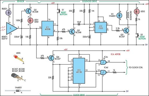
The first regulates down to 5V (for the K155D drivers) and the second regulates the 5V down to 3. 3V for the prop, eeprom, and dallas clock. The dallas clock is fairly stragithforward to connect. There`s three pins for control. It has its own crystal. I brought the BBU (battery backup) out to a header in case I want to install a battery at a later time. Next up let`s have a look at the Nixie Tubes and drivers: The tube schematic got scaled a little tiny to fit everything on the page.
You can click it for a bigger picture (as with all the other schematics on this page). We have a total for four IN-12 tubes. The cathodes are controlled by K155D (similar to 74141) Nixie Tube Drivers. The K155D is a handy chip that takes a 4-bit BCD value and grounds the appropriate cathode to light up the digit for you. You`ll notice that each K155D is connected to two tubes. That`s so we can save a little bit of part count on the board and pin count on the MCU. The anodes are controlled by a pair of transistors, a MPSA42 and a MPSA92. This is called multiplexing. All four tubes aren`t on at the same time ” we light them alternatively so fast that a human cannot tell.
To prevent ghosting, it`s important that you use a blanking interval. During the blanking interval, the anodes are turned off. Then during the display interval you turn on the appropriate cathodes (via BCD value to the K155D) and turn on one of the anodes. First of all, my plan has always been to hook a GPS up to this clock so it can set itself. That`s one of the reasons for the expansion header, so there`s a few data pins available to connect a GPS module.
I currently have a couple of Sparkfun GPS modules on order, an EM-406A and a UP501. The EM-406A is something I`ve used before. The disadvantage of it is that it requires 5 VDC power, and I didn`t leave a 5 V pin anywhere on the board. The UP501 I haven`t used. It fortunately uses 3. 3V, so I`ll be able to use the power pins on the expansion header. In both cases, I wish I`d taken the time to lay out the proper pinout on the board for connecting the GPS modules.
It`d be simpler than wiring up a custom cable to go to the expansion header. I also put the power jack facing down. This is inconvenient if the clock were to sit upright on a desk 🔗 External reference
Related Circuits
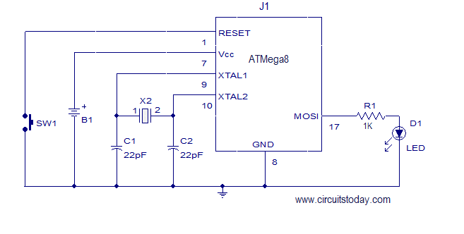
This article explains how to add a 32K external crystal/clock source to the Atmel AVR microcontroller Atmega8, including a circuit diagram and a C program. The Atmel AVR microcontroller Atmega8 is a popular choice for various embedded applications, often requiring...
Most LCD issues arise from delay routines. First, ensure proper interfacing of the LCD before proceeding with your digital clock project. A step-by-step approach is crucial. An LCD tutorial is available in the tutorial section for reference. The code...
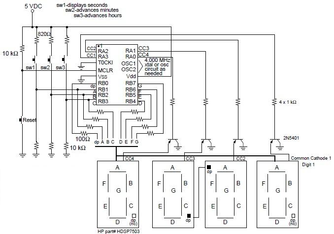
A digital clock project utilizing the PIC16C54 microcontroller can be constructed using the provided circuit diagram. This electronic project features a time-of-day clock that includes four seven-segment LED displays and three input switches. Additionally, there is a reset switch...
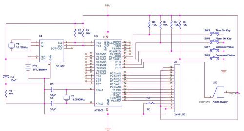
The DS1307 is a hardware real-time clock that operates using the I2C protocol. It features improved graphics with a traditional alphanumeric LCD (model HD44780). Icons indicate the status of the Alarm ON/OFF state, enhancing the visual appeal of the...
This design allows for the construction of an electromagnetically impulsed pendulum clock with a one-second beat. The prototype features a pendulum rod measuring 115 cm in length, with a bob adjusted to achieve a one-second beat. The pendulum is...
A beep or metronome-like click and/or a visible flash will indicate a one-second interval, which can be useful in various applications requiring time-delay counting in seconds. The circuit utilizes a CMOS 4024 counter/divider chip and three diodes, configured to...