
Liquid detector circuit diagram using logic gates
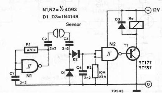
The liquid detector circuit can be constructed using a few essential components, including a Schmitt trigger inverter, diodes, a capacitor, and a relay. The Schmitt trigger inverter is responsible for generating a square wave output that serves as the alternating voltage source. This output is crucial for detecting changes in the electrical conductivity of the liquid.
The circuit begins with a power supply connected to the Schmitt trigger, which generates an alternating voltage signal. This signal is fed through diodes D1 and D2, which are arranged in a configuration to allow current to flow only when the voltage is above a certain level, thus ensuring that the capacitor C4 charges only when the conductive fluid is present between the electrodes.
Capacitor C4 plays a vital role in the timing and operation of the circuit. As the capacitor charges, its voltage rises until it reaches the threshold voltage required to activate logic gate N2. At this point, the logic gate changes its output state, energizing the relay coil. The relay acts as a switch, allowing a connected device to be powered on or off based on the presence of the conductive liquid.
Once the conductive fluid is no longer detected, the voltage across capacitor C4 decreases, and when it falls below the threshold, logic gate N2 resets, deactivating the relay. This results in the connected device being turned off, effectively creating a liquid detection system that can be used in various applications, such as overflow prevention, leak detection, or liquid level monitoring.
In summary, this liquid detector circuit is a simple yet effective solution for monitoring the presence of conductive liquids. It utilizes a combination of common electronic components, including a Schmitt trigger, diodes, a capacitor, and a relay, to create a reliable detection mechanism that can be deployed in various electronic applications.The liquid detector is a detector with liquid alternating voltage and can be built using some common electronic components. Voltage alternative for this circuit is made using a gate with Schmit trigger function, which works as an alternative power oscillator.
If between both electrodes is electrically conductive fluid as a result of recovery actio n diodes D1 and D2, capacitor C4 is charged. When the capacitor voltage reaches the switching of logic gate N2 and connects relay device connected to it. When the electrodes make no longer contact, the relay switches off the device connected to it. 🔗 External reference
Related Circuits
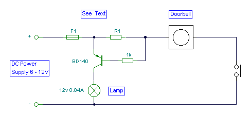
It is easy to miss the sound of a doorbell while watching TV. This circuit addresses the issue by providing a visual indication, such as a lamp or an LED. Connecting a lamp directly in parallel with the doorbell...
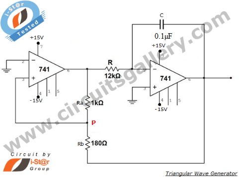
An operational amplifier-based triangular waveform generator is a simple circuit that is widely used in function generators. This circuit utilizes the 741 operational amplifier to create a triangular wave generator. The output waveform of an integrator will be triangular...
This machine utilizes the FD-CAS-923 1-stepper motor control experiment board with a 4-phase stepper motor to avoid its schematic shown in Figure 4-42a. The JK1 cop 40 core flat cable connector allows for signal arrangements compatible with EICE51 simulation...
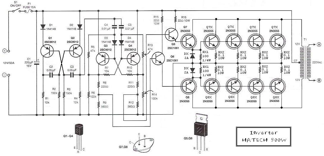
This is the schematic diagram of a 500W power inverter circuit built using 10 pieces of well-known NPN power transistors, 2N3055, to amplify the AC signal produced by a multivibrator. The frequency generator/multivibrator is also constructed using transistors. All...
A simple soft start circuit is being developed that initially routes power through a resistor or thermistor before activating the main load. The soft start circuit is designed to gradually increase the power supplied to a load, thereby minimizing inrush...
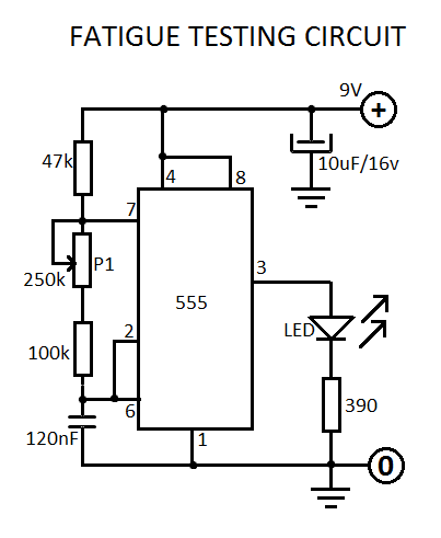
This fatigue testing circuit is straightforward and easy to assemble, designed to assess an individual's level of fatigue. Research indicates that the highest light frequency can be used as an indicator. This fatigue testing circuit operates on the principle of...
Warning: include(partials/cookie-banner.php): Failed to open stream: Permission denied in /var/www/html/nextgr/view-circuit.php on line 713
Warning: include(): Failed opening 'partials/cookie-banner.php' for inclusion (include_path='.:/usr/share/php') in /var/www/html/nextgr/view-circuit.php on line 713