
soft start circuit
The soft start circuit is designed to gradually increase the power supplied to a load, thereby minimizing inrush current and reducing stress on components. The circuit typically consists of a power source, a main load, a resistor or thermistor for initial current limiting, and a control mechanism, often implemented using a relay or a transistor.
In operation, when power is first applied, the current flows through the resistor or thermistor, which limits the current and allows for a gradual increase in voltage across the load. This component can be selected based on the desired time constant for the soft start process. As the temperature of the thermistor increases or as the voltage across the resistor rises, the resistance decreases, allowing more current to flow to the load.
The control mechanism is activated after a predetermined time or voltage level is reached. This can be achieved using a timer circuit or a microcontroller that monitors the voltage across the load. Once the soft start period is complete, a relay or a transistor is triggered to bypass the resistor or thermistor, allowing full power to be supplied to the load.
In summary, this soft start circuit effectively reduces inrush current and prolongs the life of the connected components, making it suitable for applications such as motors, power amplifiers, or any other devices sensitive to sudden power changes. Proper selection of the resistor or thermistor, as well as the control mechanism, is critical to achieving the desired performance and reliability of the circuit.Hi All, I have been trying to come up with a simple soft start circuit that routes power initially through a resistor or thermistor and then activates .. 🔗 External reference
Related Circuits
This is a small electronic switch that connects a battery to the equipment for a certain amount of time when a push-button is momentarily pressed. The ambient light level has also been considered; when it is dark, the display...
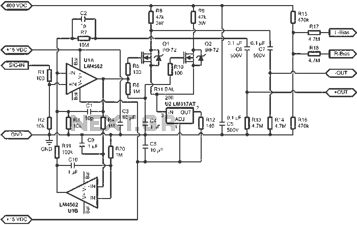
When connected to popular Stax Class 1 electrostatic headphones, the design illustrated in the figures may operate across the full audio bandwidth with a transmission voltage close to 200 Vp-p. Although the resistor divider can be modified to provide...
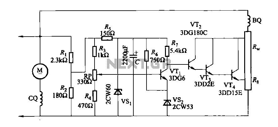
The DC generator automatic voltage regulator circuit is illustrated in Figure 7-53. This circuit is designed for a 40kW, 230V DC shunt complex machine, with a voltage change rate of up to 2.5 percent. In Figure 7-53, BQ represents...
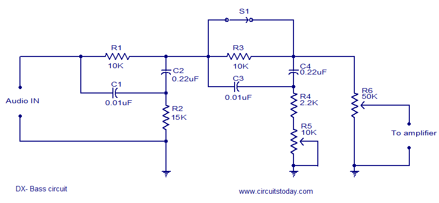
The circuit diagram of a passive DX bass circuit is presented, which is compatible with nearly all audio amplifiers. This design was created by Mr. Emmanuel Chipula from Malawi and submitted for publication. Laboratory tests confirmed satisfactory performance. Credit...
This page features a circuit that has twenty open collector outputs that turn on one at a time in a continuous sequential manner. The circuit utilizes the 74LSxx family of TTL integrated logic devices. The circuits are designed to...
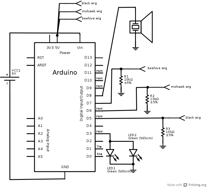
The interaction design for the singing pig was to have a different song start playing when a different wig is placed on the pig. The pig needed to stand by itself without being connected to anything else, and the...
Warning: include(partials/cookie-banner.php): Failed to open stream: Permission denied in /var/www/html/nextgr/view-circuit.php on line 713
Warning: include(): Failed opening 'partials/cookie-banner.php' for inclusion (include_path='.:/usr/share/php') in /var/www/html/nextgr/view-circuit.php on line 713