
Lithium Ion Charger 2 Cell
The described charger circuit utilizes a pulse charging method, which is efficient for various battery types. The core components include a TL431 voltage reference, a 555 timer, and two transistors for controlling the charging pulses. The TL431 serves as a precise reference voltage, ensuring that the comparator accurately detects when the battery voltage drops below the threshold of 2.5 volts. The 555 timer is configured in a monostable mode, generating a pulse that activates the transistors, allowing current to flow to the battery for a predetermined duration.
The charging current is modulated by the series resistor, which can be selected to achieve the desired charging rate. This adaptability is crucial for accommodating different battery chemistries, as each type may require specific charging profiles. The use of resistors to divide the battery voltage allows for a straightforward method of monitoring the battery's state of charge. The careful selection of these resistors is essential, particularly when charging batteries with different nominal voltages, as it directly influences the shut-off mechanism of the circuit.
In practice, the circuit's operation can be validated by substituting a large capacitor for the battery, enabling the user to observe the charging behavior without risking damage to the battery. This approach ensures that the circuit's performance can be fine-tuned before connecting it to an actual battery. Overall, this charger design is versatile and can be adapted for various applications, provided that the necessary adjustments to component values are made to suit the specific battery being charged.The charger operates by supplying a short current pulse through a series resistor and then monitoring the battery voltage to determine if another pulse is required. The current can be adjusted by changing the series resistor or adjusting the input voltage. When the battery is low, the current pulses are spaced close together so that a somewhat con stant current is present. As the batteries reach full charge, the pulses are spaced farther apart and the full charge condition is indicated by the LED blinking at a slower rate. A TL431, band gap voltage reference (2. 5 volts) is used on pin 6 of the comparator so that the comparator output will switch low, triggering the 555 timer when the voltage at pin 7 is less than 2.
5 volts. The 555 output turns on the 2 transistors and the batteries charge for about 30 milliseconds. When the charge pulse ends, the battery voltage is measured and divided down by the combination 20K, 8. 2K and 620 ohm resistors so that when the battery voltage reaches 8. 2 volts, the input at pin 7 of the comparator will rise slightly above 2. 5 volts and the circuit will stop charging. The circuit could be used to charge other types of batteries such as Ni-Cad, NiMh or lead acid, but the shut-off voltage will need to be adjusted by changing the 8.
2K and 620 ohm resistors so that the input to the comparator remains at 2. 5 volts when the terminal battery voltage is reached. For example, to charge a 6 volt lead acid battery to a limit of 7 volts, the current through the 20K resistor will be (7-2. 5)/ 20K = 225 microamps. This means the combination of the other 2 resistors (8. 2K and 620) must be R=E/I = 2. 5/ 225 uA = 11, 111 ohms. But this is not a standard value, so you could use a 10K in series with a 1. 1K, or some other values that total 11. 11K Be careful not to overcharge the batteries. I would recommend using a large capacitor in place of the battery to test the circuit and verify it shuts off at the correct voltage.
🔗 External reference
Related Circuits
Colour temperature refers to the tonal quality or shade of light. White light, for instance, is subjective and available in various hues. This guide aims to assist in identifying the most suitable shade for specific situations. A "warm" white...
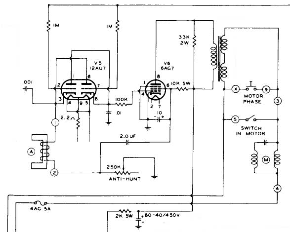
The motor control chassis lacks a coaxial input, raising doubts about the presence of composite sync, particularly given the length of the cables (5 or 6 feet), which may eliminate the possibility of a sync pulse for the red...

TCA440 is an AM receiver circuit designed for long wave (LW), medium wave (MW), and short wave (SW) applications in both battery-operated and line-operated radio receivers. It features an RF pre-stage with automatic gain control (AGC), a balanced mixer,...
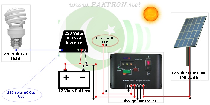
A solar charge controller is an electronic device used in solar system installations to regulate the amount of charge directed toward a battery from a solar panel. Charge controllers come in various types and ratings. The term "charge controller"...
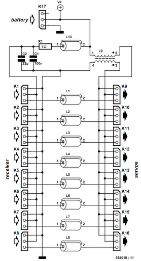
Receiver interference is a common issue among model builders. Preventive measures, such as ferrite beads fitted to servo cables, are frequently employed in larger models and electrically driven models to prevent the cables from acting as antennas and radiating...
How the circuit works. The circuit comprises a non-inverting amplifier with a final output buffer stage or voltage follower for impedance matching. The described circuit functions as a non-inverting amplifier, which is designed to amplify an input voltage while maintaining...