
BMW40 Ibus tuner Amp Modification
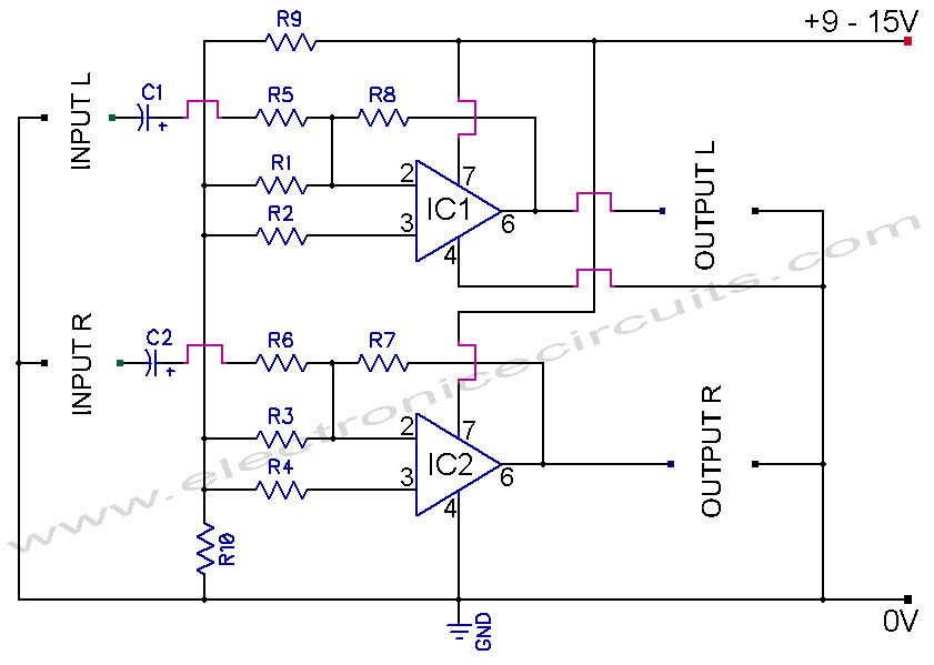
The described circuit functions as a non-inverting amplifier, which is designed to amplify an input voltage while maintaining its phase. This configuration is ideal for applications where a high input impedance and low output impedance are required. The non-inverting amplifier utilizes operational amplifiers (op-amps) to achieve the desired gain, which can be set by external resistors.
In this circuit, the gain (Av) is determined by the resistors connected to the op-amp, following the formula Av = 1 + (Rf/Rin), where Rf is the feedback resistor and Rin is the resistor connected to the input. This allows for precise control over the amplification level.
Following the amplification stage, a voltage follower or buffer stage is employed. This is typically implemented using another op-amp configured in a unity-gain configuration. The purpose of the buffer is to provide impedance matching between the high-impedance output of the amplifier and the load, which may have a lower impedance. The voltage follower ensures that the output voltage remains equal to the input voltage while providing the necessary current drive capability without affecting the performance of the preceding amplifier stage.
The entire circuit is powered by a dual power supply, providing both positive and negative voltage rails to the op-amps, which is essential for proper operation. Bypass capacitors are also included near the power supply pins of the op-amps to filter out any noise and ensure stable operation.
In summary, this circuit effectively amplifies an input voltage while maintaining integrity and providing the necessary impedance matching for subsequent stages or loads. It is commonly used in audio processing, sensor signal conditioning, and other applications requiring precise voltage amplification.How the circuit worksh1. Your title here The circuit comprises a non inverting amplifier with a final output buffer stage or voltage follower for impedance matchin.. 🔗 External reference
Related Circuits
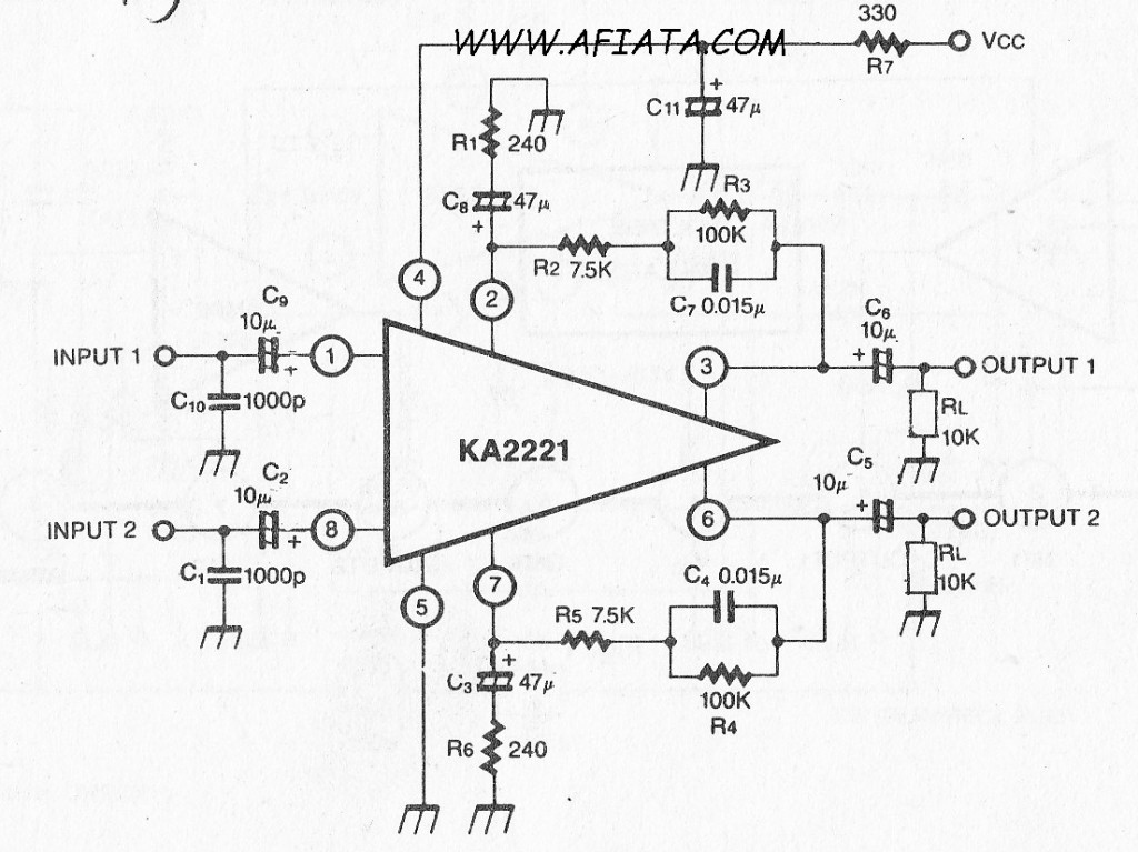
Audio amplifier circuit board with a dual low noise equalizer amplifier. The KA2221 is a monolithic integrated circuit that features 2-channel low noise amplifiers and a regulated power supply designed for car stereos. Key features include suitability for car...

Author Mazi Hosseini describes a simple, low-cost voltage-controlled current source using two operational amplifiers that provides a good range of current and maximum load. The circuit described by Mazi Hosseini utilizes two operational amplifiers (op-amps) to create a voltage-controlled current...
This amplifier is designed to be as flexible as possible, with no bad habits. Indeed, it will operate stably with supply voltages as low as +/-5V (completely pointless, but interesting), all the way to the maximum supply voltage of...
741 Stereo PreAmplifier Circuit Diagram. This preamp circuit provides better than 20dB gain in each channel. PARTS LIST R1 -.. The 741 stereo preamplifier circuit is designed to amplify audio signals with a gain of over 20 dB in each...

This is a simple headphone amplifier circuit designed to drive headphones when a music player lacks sufficient power. The circuit is straightforward and utilizes only three transistors. The first transistor, Q1 (BC 239), along with its associated components, functions...
This series-feedback configuration of compounds provides a high input impedance and stable, wide-band gain video amplifier suitable for general-purpose applications. It features low capacitance and high impedance. The described video amplifier circuit utilizes a series-feedback topology to achieve high input...