
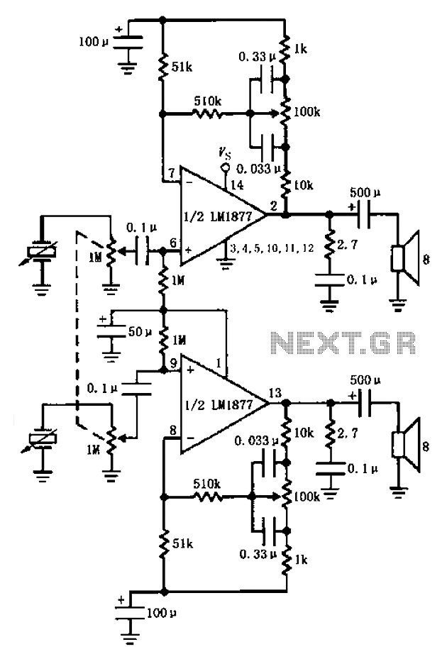
LM1877 amplifier having a control circuit diagram of the bass
The circuit utilizes the LM1877 integrated circuit, which is designed for audio amplification applications, particularly in bass-heavy environments. The configuration allows for effective manipulation of audio signals, ensuring that both the left and right channels are balanced and provide a rich sound output. The use of cermet potentiometers is advantageous due to their stability and longevity, making them suitable for audio applications where precision is critical.
In this setup, the two 1M potentiometers not only control the volume but also help in maintaining the integrity of the audio signal by minimizing distortion. The coupling capacitors of 0.1 µF act as high-pass filters, eliminating unwanted low-frequency noise that could interfere with the audio clarity. The feedback loop involving the 100k potentiometers is crucial for fine-tuning the bass response, allowing the user to adjust the tonal quality of the sound output to their preference.
The addition of 2.7 ohm resistors in parallel with the speakers serves to dampen any high-frequency oscillations that may arise, enhancing the overall sound quality by providing a smoother response. The capacitors in this configuration act as bypass elements, ensuring that high-frequency noise is filtered out before reaching the speakers, resulting in a cleaner sound reproduction.
Overall, this circuit design effectively combines various components to create a robust bass amplification system suitable for performance settings, where sound quality and control are of utmost importance. Bass player with a stereo control as shown by LM1877 amplifier circuit configured. Cermet stereo microphone pickup stereo turntable on the left and right channel audio signals through two 1M potentiometer input, respectively, by two 0.1 F capacitive coupling is applied to the input of LM1877 6,9 feet, amplified by two, 13 feet respectively output, respectively, to the left and right channel speaker. Among them, two 1M potentiometer for the volume potentiometer, two potentiometers linkage for adjusting the volume.
1 and connected to two feet 1M resistor is used to set the amplifier operating point of DC bias, and coupling capacitors and 0.1 F input high-pass filter. Connected in a feedback loop between the amplifier 2 feet and 7 feet 100k potentiometer (Similarly, connected between the amplifier 13 feet and 8 feet feedback loop 100k potentiometer) for the bass control potentiometer.
Respectively, of the left and right channel loudspeaker parallel 2.7 resistor, 0.1 F capacitor for filtering high frequency noise.
Related Circuits
This receiver is designed around the widely used ZN414 integrated circuit (IC) and operates within the AM band, covering frequencies from 550 to 1600 KHz. To utilize the receiver for Longwave frequencies, it is necessary to replace the coil...
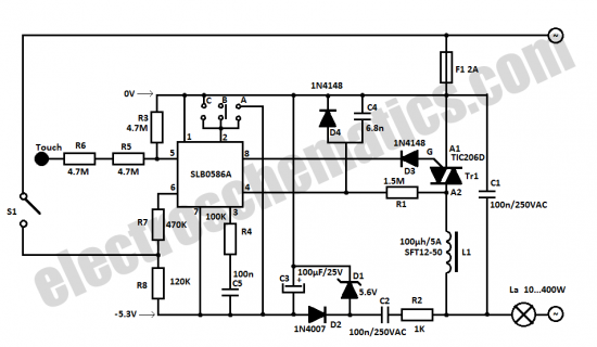
The SLB0586A integrated circuit from Siemens can be utilized to construct a straightforward touch light dimmer circuit, enabling the user to modify the intensity of a lamp. This circuit also incorporates a TIC206D component. The SLB0586A is a specialized touch-sensitive...
Do not drink and drive. Wishing you a safe journey home. Language Integrated Circuits. Language Integrated Circuits (LICs) are specialized electronic components designed to facilitate the processing of language-based data within various applications. These circuits integrate multiple functions, such as...

This stereo amplifier utilizes the NE5517/A and features an excellent tracking accuracy of 0.3 dB, which is typical. The offset can be adjusted using the potentiometer, Rp. For AC-coupled amplifiers, the potentiometer can be substituted with two 5.1 k...
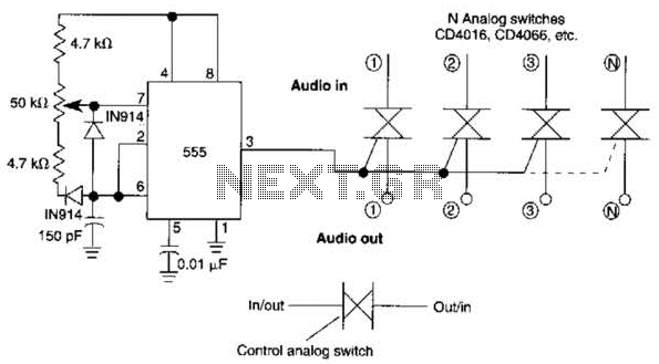
A 555 timer can be configured to simulate a multi-gang potentiometer by controlling the mark-space ratio. The switching rate should be at least twice the maximum expected signal frequency that the potentiometer has to handle. The 555 timer is an...
The objective is to enhance information transmission through the distribution of articles. For any issues related to article content, copyright, or other concerns, please reach out via email to [email protected] within 15 days. Prompt action will be taken to...