
Digital Multiple-Gang Potentiometer Control Circuit

The 555 timer is an integrated circuit widely used in various applications, including timing, pulse generation, and oscillation. When configured in astable mode, it can create a square wave output that can effectively simulate the behavior of a multi-gang potentiometer. In this configuration, the duty cycle of the output waveform is adjustable, allowing for control over the mark-space ratio. By varying the resistances and capacitance in the circuit, the output pulse width can be manipulated, effectively simulating different resistance values.
To achieve optimal performance, it is crucial to set the switching rate of the 555 timer to be at least twice the maximum frequency of the signal that the simulated potentiometer will handle. This ensures that the output can accurately follow the input signal without distortion, maintaining the integrity of the waveform. The formula for calculating the frequency of oscillation in astable mode is given by:
\[ f = \frac{1.44}{(R1 + 2R2)C} \]
where \( R1 \) and \( R2 \) are the resistances connected to the timing capacitor \( C \). Adjusting these resistances allows for fine-tuning of the output frequency and duty cycle.
In practical applications, the output of the 555 timer can be fed into a low-pass filter or directly into the input of an analog circuit, depending on the specific requirements. The simulated multi-gang potentiometer can be utilized in various electronic devices where variable resistance is needed, such as in audio applications for volume control or in sensor applications where adjustable thresholds are required.
Overall, utilizing a 555 timer to simulate a multi-gang potentiometer provides a versatile and adjustable solution for electronic circuit design, enabling precise control over resistance values and signal modulation. A 555 timer can be configured to simulate a multi-gang potentiometer by controlling the mark-space ratio. The switching rate should be at least twice the maximum expected signal frequency the potentiometer has to handle.
Related Circuits
This is a single-channel (on/off) universal switch that can be used with any infrared remote control operating within wavelengths of 850-950 nm. The single-channel universal switch functions as a simple on/off control mechanism, allowing users to operate electronic devices remotely...
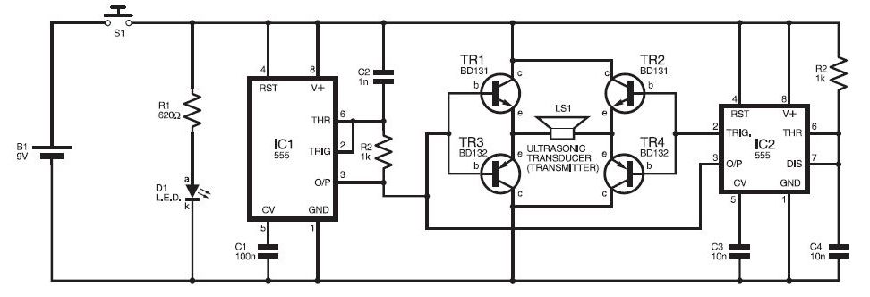
This ultrasonic sensor circuit consists of a set of ultrasonic receivers and transmitters that operate at the same frequency. When an object moves within the covered area, the circuit's balance is disturbed, triggering the alarm. The ultrasonic circuit is...
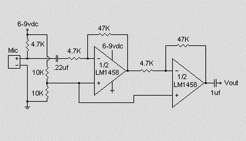
This is a simple preamplifier circuit designed for an electret condenser microphone, utilizing an LM1458 dual op-amp integrated circuit (IC). The circuit amplifies the audio signal from the condenser microphone, allowing it to be used as an input for...
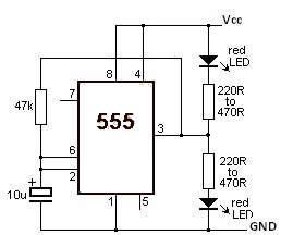
This LED flasher circuit utilizes a 555 timer integrated circuit (IC). The circuit diagram is straightforward and requires only a few external components. When operational, the red LEDs will flash sequentially at a predetermined frequency, similar to the indicators...
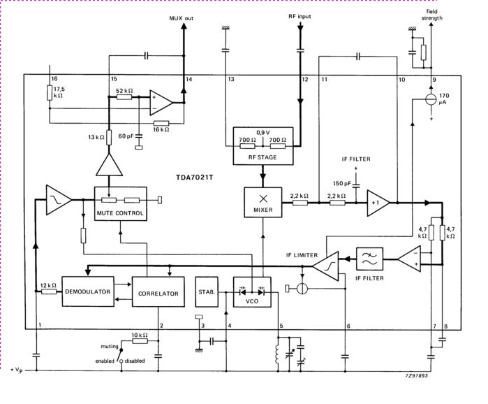
The TDA7021T integrated radio receiver circuit is designed for portable radios, both stereo and mono, where minimal peripheral components are essential for achieving small dimensions and low cost. It is fully compatible. The TDA7021T is a highly integrated radio receiver...
The Heater Fan Controller is designed around the PIC12F675 microcontroller. It reads a 10k linear potentiometer and generates appropriately timed pulses to control the DC motor that operates the fan. The lowest setting completely cuts off the power. This...