
Lock start puter circuit
A comprehensive electronic schematic description can be outlined as follows. The main objective of this circuit is to control the power to the ACC line based on the state of the car locks. The system utilizes a latched relay configuration, where the relay is triggered by a negative pulse from the car lock mechanism. This pulse activates the relay, allowing current to flow to the ACC line, which is critical for powering the startup/shutdown controller of the PC.
The circuit design includes two relays, with the first relay being responsible for latching the circuit on activation. The second relay, as suggested, should be replaced with one that features a Normally Closed (N.C.) position. This configuration ensures that when the ACC line is energized, the output of the relay is maintained until the ACC line is turned off, effectively controlling the power to the circuit.
To address the issue of power interruption, diodes should be incorporated in the design to prevent backflow of current, ensuring that the circuit operates safely and effectively. The relay's coil should be connected to a constant 12 volts, while the door unlock wire should be connected to ground. This arrangement allows the relay to close when the unlock signal is received, activating the circuit.
Additionally, the second relay must be connected to ground, with inputs from the first relay, the parallel port output from the PC, and the ACC line. This configuration allows for multiple triggering conditions, ensuring that either the unlock signal or the ACC activation can initiate the PC's startup sequence. The suggested delay in the software to wait for the ACC line to stabilize before activating the output pin is a prudent approach to prevent unintended behavior during startup.
Overall, the design aims to create a reliable and responsive circuit that integrates with the vehicle's locking system, enhancing the functionality of the PC startup process while ensuring safe operation through proper relay and diode configurations.Hi everyone. I have a quick question. I`m trying to devise a circuit that works off my car locks. Basically they get a negative pulse, which starts a latched relay, which will power up the ACC line going to the startup/shutdown controller. I`ve included a picture of my current circuit but I`ve noticed one problem. In order to stop the chained relay (stuck-on) action you need to kill the 12volts going to it. So, I have it rigged to pin1 of the parallel por, t though a molex conntor would work two. Here`s the issue: The moment the PC turns on the ACC line turns back off. This in turn tells the controller to shut down. Hmmph. I was wondering if I throw it on pin 2 or 3, and have a program that waits oh. 2 minutes, then turns ON the pin, if it`ll work. Only problem is that start-up sequence tends to be a bit of a pain, and flashes the pins. Any ideas Many of us do something like this, but with the ACC turning it on. If your door unlock is long enough to get the PC to output 12V, it will hold the relay closed until it shuts off. Just make sure the diodes are in the right direction and it will be safe. They can be small 1/2 amp generic ones. That makes sense, but I just redesigned the circuit while I walked the dog. BTW: What relays are you using You have two relays hooked up in series there, and it seems to me 12v wouldnt do it.
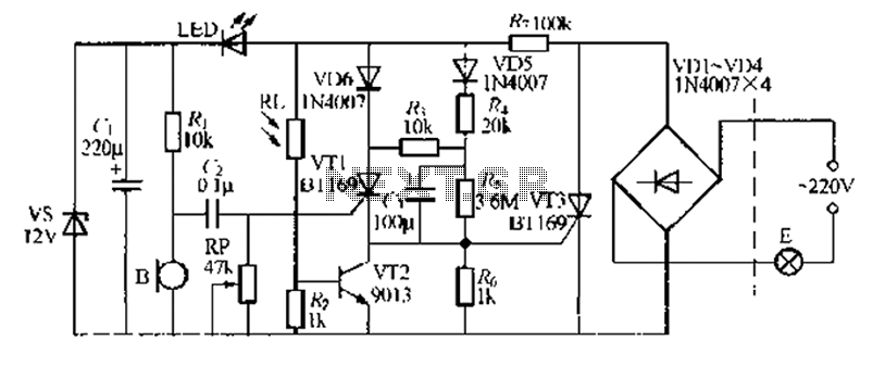
Unless there 5v relays Replace the bottom relay/ parallel port bit with a relay that has a N. C. position. When it`s N. C. the rest of the circuit gets 12V. Have the relay hooked to the ACC line, so when the ACC goes on, the circuit loses 12V. Have the circuit`s output and the ACC line hooked together with a few diodes. Voila. Oh, BTW, about the locks being long enough. I`m just adding electric locks now. It`s a set of 4, and I only have two doors I can hook it up to in my minivan. Can`t run a wire into the 3rd door. So I have plenty of extra places to plug into. Additonally, I have 2 extra push/pull solenoids. If I don`t find something for them soon, I`m gonna sell them off here. I am trying to understand your original schematic. Can you please clarify what the things in the blue square, and explain what the stuff in the red square does, in particular, connecting the - output of the computer parralel port with the postive going into the relay in the red box. I love the French language. especially to curse with. Nom de Dieu de putain de bordel de merde de saloperies de connards d`enculG©s de ta mG¨re. You see, it`s like wiping your * with silk, I love it. I`ve never really used automotive relays, so I might be wrong on that. I think the negative pulse on the unlock just connects to gnd, so for the positive you would connect the relay coil to constant 12v and the door unlock wire would ground it and close that relay.
The contacts would connect to 12v and output to that fist diode. I think all that`s right. The second relay doesn`t look right though. The coil should be connected to gnd and 3 different inputs (with diodes on each one): The pulse from the 1st relay, output from the PC, and ACC. The contacts should connect to constant 12v and to the PSU. This way the unlock or ACC going on would turn on the PC and the PC will hold it on. The parallel port could connect to ACC. If you`re writing your own software, you can just ignore if the ACC is low when it first starts and wait a couple minutes before assuming the key just never will be turned on.
🔗 External reference
Related Circuits
The original scale on the voltmeter ranged from 0 to 30 volts. A new scale was created by removing the old scale from the meter and scanning it into a graphics editing software on a computer. The old numbers...
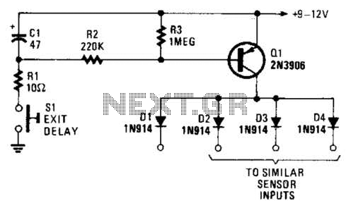
Depressing SI charges CI to the supply voltage. This biases Q1 on via bias resistors R2 and R3. A voltage is available for the duration of the delay period to hold off the alarm circuit. CI can be increased...
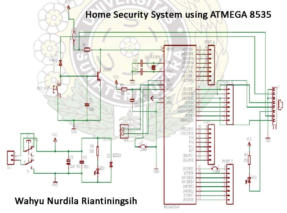
The Atmega 8535 Color Conversion to Frequency project utilizes instrumentation technology to recognize colors, also known as a color sensor, which is essential in various industrial applications. This sensor has multiple uses, ranging from the paint industry to satellite...
A relatively simple circuit for controlling a stair walkway light with a delay feature. The circuit has a drawback in that the voice activation is somewhat less sensitive, making it sometimes difficult to trigger with general conversation. However, it...
Sawtooth wave generators using opamp are very common. But the disadvantage is that it requires a bipolar power supply. A sawtooth wave generator can be built using a simple 555 timer IC and a transistor as shown in the...
This is a remote tester circuit designed to test TV and other remote controls. The circuit is simple and utilizes only a few components. The infrared sensor used in the circuit is the TSOP1738. When the infrared waves are...
Warning: include(partials/cookie-banner.php): Failed to open stream: Permission denied in /var/www/html/nextgr/view-circuit.php on line 713
Warning: include(): Failed opening 'partials/cookie-banner.php' for inclusion (include_path='.:/usr/share/php') in /var/www/html/nextgr/view-circuit.php on line 713