
Low cost 20 w audio amplifier
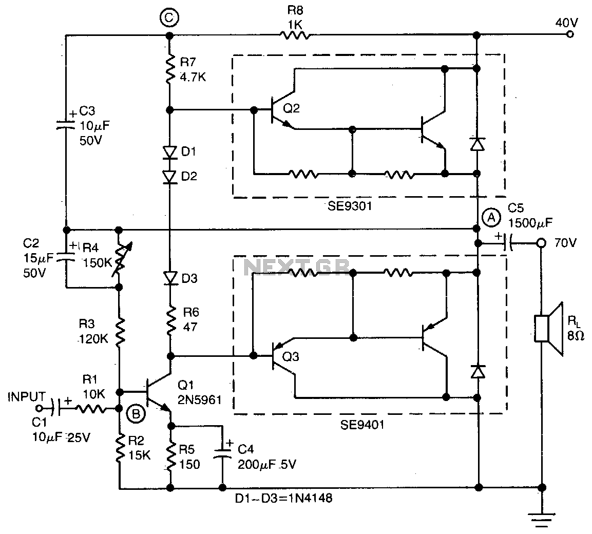
The audio amplifier circuit utilizes a push-pull configuration to efficiently drive an 8-ohm load, delivering a robust 20 W output. The choice of TO-220 Darlington transistors for the output stage provides high current gain, allowing for effective amplification with minimal distortion, particularly in the specified frequency range. The inclusion of the 2N5961 transistor as the voltage gain stage is critical for achieving the desired performance metrics, as it provides the necessary drive to the output transistors while also allowing for effective feedback mechanisms.
The feedback network, established at the base of Q1, plays a significant role in stabilizing the amplifier's performance. The AC and DC feedback ensures linearity and minimizes distortion across the operating range. The input resistance of 10 kΩ is suitable for interfacing with standard audio sources, ensuring compatibility and ease of use.
The center voltage at point A, adjustable via resistor R4, allows for fine-tuning of the amplifier's operating point, optimizing performance based on specific application requirements. The bootstrap circuit connected to the collector of Q1 enhances the drive capability for Q2, ensuring that the output stage receives adequate voltage for linear operation. The constant voltage across R7, established by the bootstrap arrangement, functions as a current source, which is crucial for maintaining consistent output characteristics.
Furthermore, the inclusion of diodes D1-D3 within the circuit is essential for mitigating crossover distortion, particularly at low signal levels. These diodes work in conjunction with R7 to create a more linear response during the transition between the output stage's active and inactive states, promoting overall sound quality and fidelity.
This audio amplifier design exemplifies a balance of simplicity, cost-effectiveness, and performance, making it an excellent choice for various audio applications where high-quality amplification is required.This simple inexpensive audio amplifier can be constructed using a couple of T0-220 monolithic Darlington transistors for the push-pull output stage. Frequency response is fiat within 1 dB from 30 Hz to 200 kHz with typical harmonic distortion below 0%.
The amplifier requires only 1 Vrms for a full 20 W output into an 8 ohm load. Only one other transistor is needed, the TO-92 low-noise high-gain 2N5961 (Ql), to provide voltage gain for driving the output Darlingtons. Its base (point B) is the tie point for ac and dc feedback as well as for the signal input. Input resistance is 10 K The center voltage at point A is set by adjusting resistor R4. A bootstrap circuit boosts the collector supply voltage of Ql (point C) to ensure sufficient drive voltage for Q2. This also provides constant voltage across R7, which therefore acts as a current source and, together with diodes D1-D3, reduces low-signal crossover distortion.
🔗 External reference
Related Circuits
The notch filter can be integrated into nearly any receiver to attenuate a specific frequency by more than 30 dB. This filter is particularly useful for diminishing heterodynes and whistles. A notch filter, also known as a band-stop or band-reject...

The circuit operates as a unijunction transistor relaxation oscillator. The base of the lower PNP transistor is biased at approximately half of the supply voltage. As the 100pF capacitor charges through the 1GΩ resistor, the base of the upper...
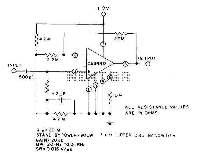
This circuit utilizes the low power leakage, high input impedance, frequency response, and capacitance characteristics of the CA3440 operational amplifier. Only one input coupling capacitor of 500 pF is required to attain a -3 dB low frequency response at...
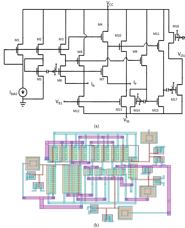
A comprehensive design procedure is proposed for the development of Field-programmable/Reconfigurable Analog Integrated CMOS circuits. Instead of relying on iterative simulation steps to meet design specifications by adjusting the W/L ratios of the FETs, first-order classroom equations are utilized...
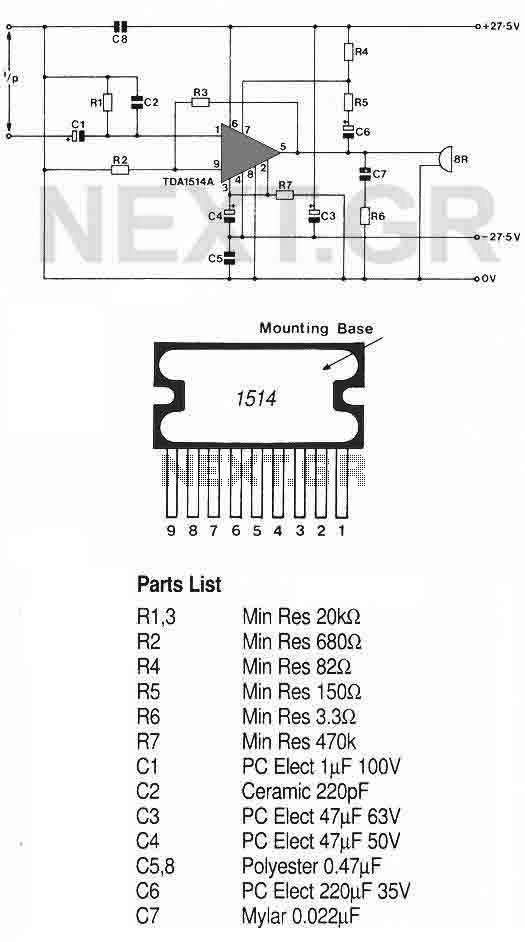
This high-quality audio amplifier is based on the TDA1514A, a 9-pin flat package integrated circuit. The heatsink must be insulated from the ground. The amplifier can deliver 40 watts into an 8-ohm load with a 27.5-volt power rail or...
Feedback in a public address amplifier should be avoided. The ideal solution is to adjust the positions of the microphone and speaker; however, this is not always feasible in many situations. A frequency shifter that alters the output frequency...