
Ultra Low Current Oscillator

The unijunction transistor (UJT) relaxation oscillator circuit typically consists of two transistors: one PNP and one NPN. The PNP transistor is configured to provide a stable reference voltage, while the NPN transistor acts as the switching element. The circuit relies on the charging and discharging of the capacitor, which is key to generating oscillations.
In this configuration, the 100pF capacitor is charged through the 1GΩ resistor, creating a time constant that determines the frequency of oscillation. The charging process continues until the voltage across the capacitor reaches a threshold level sufficient to forward bias the base-emitter junction of the NPN transistor. This forward biasing leads to a rapid increase in collector current, which subsequently discharges the capacitor quickly, causing the voltage to drop.
Once the capacitor discharges below a certain level, the NPN transistor turns off, and the cycle repeats. The frequency of oscillation can be adjusted by varying the capacitance or resistance values in the circuit. This type of oscillator is often used in applications requiring low-frequency square wave signals, such as in timing circuits, tone generation, and clock pulses for digital circuits.
The overall behavior of the circuit can be analyzed using the time constant formula τ = R × C, where τ is the time constant, R is the resistance, and C is the capacitance. The resulting oscillation frequency can be approximated by the formula f = 1 / (2πτ), allowing for precise control over the output frequency by selecting appropriate component values.The circuit functions like a unijunction transistor relaxation oscillator. The base of the lower PNP transistor is biased at roughly half supply. As the 100pF capacitor is charged up through the 1G resistor, the base of the upper NPN transistor reaches a critical voltage, which begins to forward bias the base-emitter junction . 🔗 External reference
Related Circuits
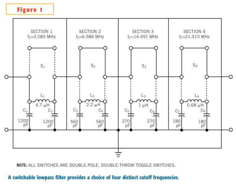
In an adjustable lowpass filter, each filter section uses commonly available components. This example uses filter-section cutoff frequencies for standard inductors and capacitors without the need for any extra components in series or parallel. Fixed inductors are Coilcraft 90...
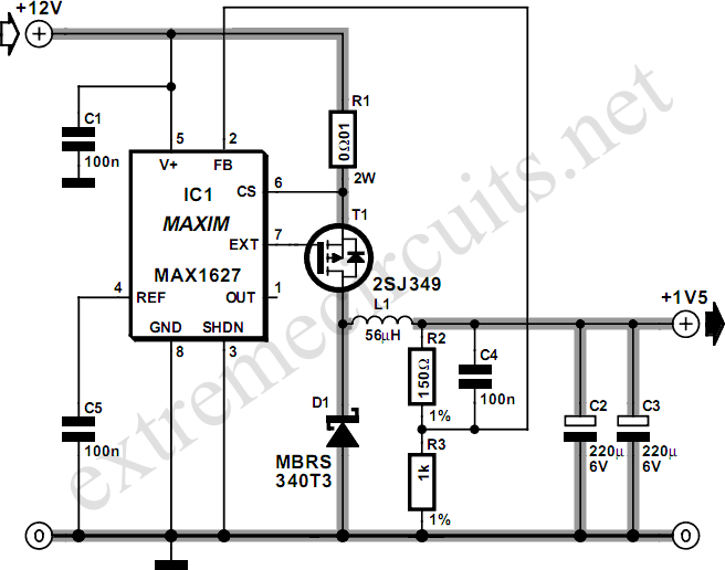
Most small internal combustion engines used in model building utilize glow plugs for starting. However, glow plugs operate at 1.5 V, while components like fuel pumps, starter motors, and chargers typically operate at 12 V. This discrepancy necessitates a...
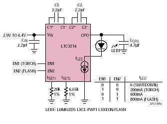
An ultralow dropout current source maintains accurate LED current at very low ILED voltages. Automatic mode switching optimizes efficiency by monitoring the voltage across the LED current source and switching modes only when ILED dropout is detected. The LTC3216...
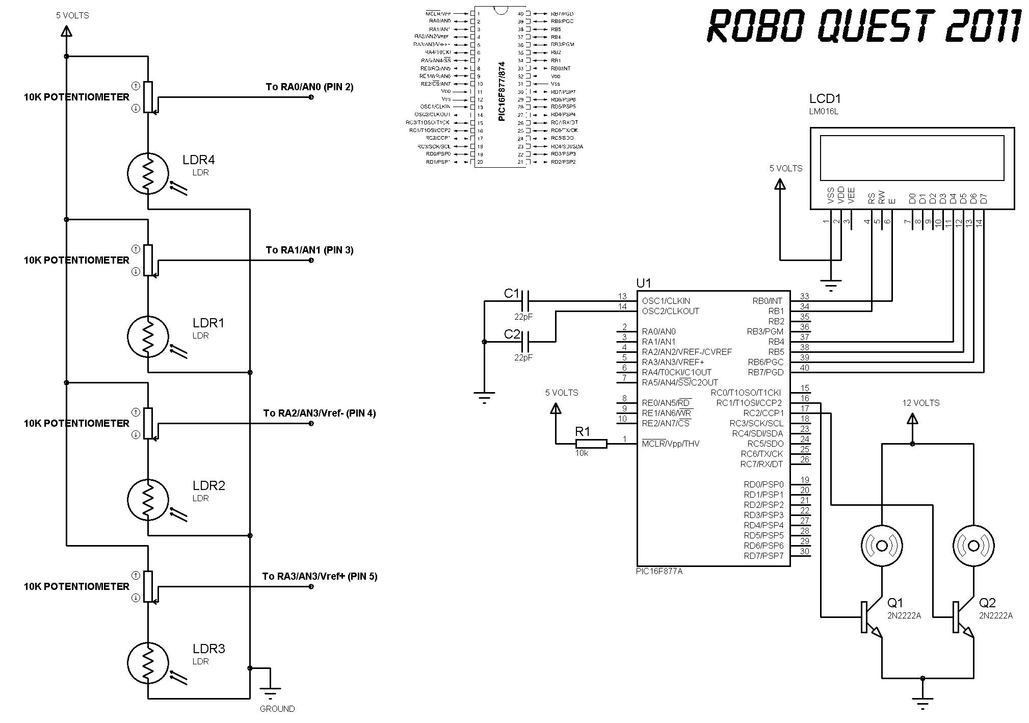
Lectures on line following robots consist of multiple sessions, including Lecture 1 (a), Lecture 1 (b), and Lecture 1 (c). A concept diagram is provided for a 1 cm line following robot, along with a schematic for a robot...
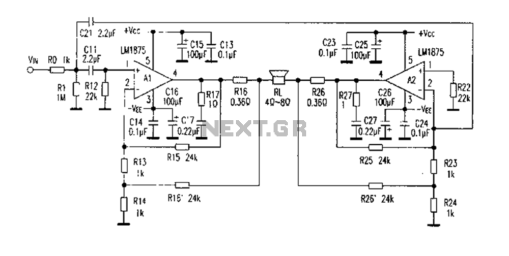
The DC current negative feedback BTL circuit illustrated in Figure 2 eliminates the standard BTL circuit capacitors C12 and C22, which affects the DC characteristics of the circuit. Resistors R16 and R26 function as sampling resistors, while R15, R16,...
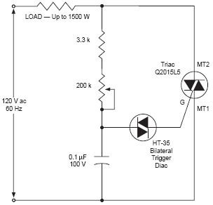
The DIAC, or diode for alternating current, is a trigger diode that conducts current only after its breakdown voltage has been momentarily exceeded. Most DIACs are utilized in applications requiring a switching function in AC circuits. The DIAC is a...