
Low Cost Precision Light Control / Dimmer
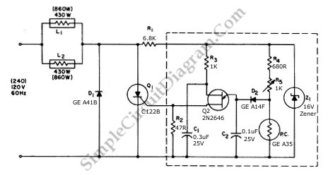
The circuit employs a phase control technique, which involves adjusting the phase angle of the AC voltage applied to the load. This method is particularly effective for varying the power delivered to resistive loads, such as incandescent lamps. The controlled half-plus-fixed half-wave approach combines elements of both half-wave and full-wave control, providing a smoother transition between power levels and reducing flicker in the lamp output.
The schematic typically includes a triac or a thyristor as the primary switching device, which is triggered at a specific phase angle determined by a control circuit. A zero-crossing detector may be integrated to ensure that the triac is triggered at the optimal point in the AC cycle, minimizing electromagnetic interference and improving efficiency.
Additional components such as resistors, capacitors, and possibly an opto-isolator may be included in the control circuit to provide isolation and to shape the control signal. The use of feedback mechanisms can enhance stability and accuracy in power regulation, ensuring that the lamp load operates effectively across the desired range.
Overall, this circuit design is suitable for applications requiring precise control of incandescent lighting, allowing for energy savings and improved user comfort through adjustable brightness levels.Using a the controlled-half-plus-fixed-half-wave phase control method, this circuit can regulate an 860 a watt lamp load from half to full power. This circuit.. 🔗 External reference
Related Circuits
The circuit involves the switching of feedback resistors for an operational amplifier (op-amp) that is driven by a Radio Shack 276-115 selenium solar cell, resulting in a multirange linear light meter. A 1000-megohm resistor is utilized for the highest...
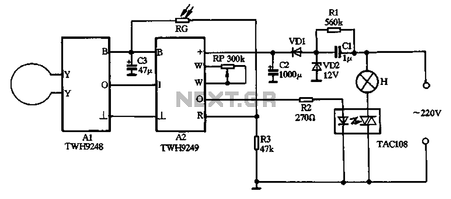
The circuit operates on 220V AC input and utilizes a CL buck converter, a VDI rectifier, and a VD2 regulator along with a filter capacitor (C2) to provide a stable 12V DC output for module A2. Module A2 includes...
The circuit activates a 20-watt lamp when the contacts are touched, provided that the skin resistance is approximately 2 Megohms or lower. The circuit on the left employs a power MOSFET that turns on when the voltage between the...
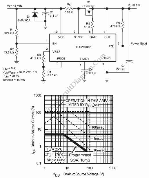
This is a positive high-voltage hot swap controller circuit with a power limiter. This circuit utilizes the TPS2491 or TPS2490, as both of them have specific features. The positive high-voltage hot swap controller circuit is designed to safely connect and...
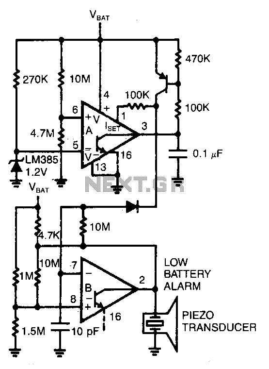
Comparator A detects when the supply voltage drops to 4 V and enables comparator B to drive a piezoelectric alarm. More: Is: 6V at 45μA, Is: 3.8V at 1μA, f: 3kHz The circuit utilizes two comparators to monitor supply voltage...
This is a power supply circuit that produces a voltage range of 12 to 24 V. It is straightforward, requiring only a bridge rectifier, a filter capacitor, and a transformer, without the need for a regulator. A bridge rectifier...