
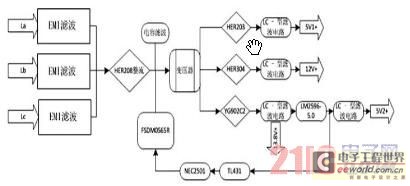
Low Voltage Power Supply

The power supply circuit described operates within a voltage range of 12 to 24 V, making it versatile for various electronic applications. The bridge rectifier, consisting of four diodes, is essential for converting the alternating current (AC) from the transformer into direct current (DC). This full-wave rectification process enhances efficiency by utilizing both halves of the AC waveform, resulting in a smoother DC output. The filter capacitor serves to smooth out the rectified voltage, reducing ripple and providing a more stable output.
The absence of a regulator simplifies the design, making it suitable for applications where precise voltage regulation is not critical. However, caution is emphasized due to the lack of isolation from the mains supply, which poses a safety risk during operation. The circuit's capability of delivering 15 VDC at 3A indicates its suitability for powering various devices, including sensors, microcontrollers, and other low to moderate power electronics.
In scenarios where a regulated output is necessary, integrating a linear regulator after the rectification process can provide a lower voltage output. While this method is simple, it does incur power losses due to heat dissipation in the regulator, which must be managed through adequate thermal design.
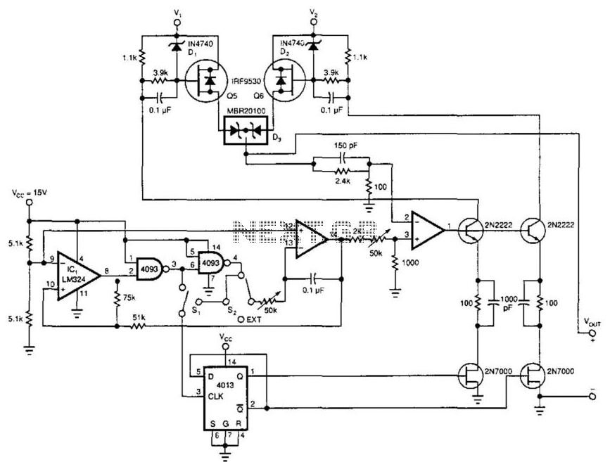
The inclusion of a Crowbar circuit enhances the overall reliability of the power supply by protecting the load from overvoltage conditions. This is particularly important in applications where sensitive components are used. The zener diode in the Crowbar circuit acts as a voltage clamp, diverting excess voltage away from the load and preventing potential damage.
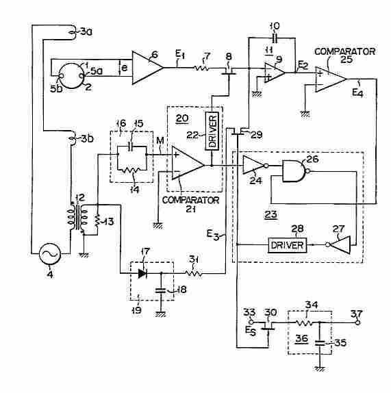
The compact power factor controller is designed to optimize the power factor of the circuit, which is crucial for improving energy efficiency and reducing electrical losses. By stabilizing the electrical demand, this circuit ensures that the power supply operates efficiently across various load conditions.
Overall, the described power supply circuit is a fundamental design that highlights essential components and considerations in power electronics, providing a foundation for further enhancements and applications in more complex systems.This is a power supply circuit that produce voltage 12 to 24 V. It is very simple, doesn`t need regulator just bridge rectifier, filter capacitor and transformer. A bridge rectifier makes use of four diodes in a bridge arrangement to achieve full-wave rectification. This circuit will give you 15 VDC at up to 3A. WARNING: Don`t touch any part of th e circuit when the circuit is running (connected to the powerline), this circuit is not isolated from mains supply. This is transformerless power supply circuit. This circuit is used to generate fixed voltage power Continue reading †’. Applying the filtered and rectified AC input to a high-input-voltage linear regulator is the simplest way to produce low current level from an AC source.
However, it will causes the power dissipation in the regulator. The power dissipation can be Continue reading †’. A diode bridge, a step down transformer a linear regulator(U1) and some filtering capacitors can be used to build a Linear power supply. This circuit has some advantages such as this circuit has high output current and can give multiple Continue reading †’.
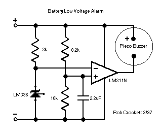
This is a The Crowbar circuit. This circuit is used to prevent the load from damaging. This circuit utilize a zener diode. The regulator steps down the 12V input to 5V. The load will damage when the regulator is fail Continue reading †’. This is compact power factor controller circuit. It stabilizes device`s electrical demand to give best power factor characteristic of many types of loads. In many application, a direct rectification of the AC line followed by bulk capacitor filtering is used Continue reading †’.
🔗 External reference
Related Circuits
Currently, the switching power supply boasts high performance with an efficiency of 75%. The efficiency of single-scale integration switching power supplies has exceeded 90%. This advancement addresses energy concerns and enhances the performance of numerous energy-saving electrical devices. The...
This power booster operates as a high-efficiency power multiplexer or, when supplied with an external signal source, as a high-power linear amplifier. For driving a load with a high-power square wave, the circuit alternately draws power from two external...
Electromagnetic flow meter: How to measure fluid flow using a magnetic field. An electromagnetic flow meter is a device used to measure the flow rate of conductive fluids by utilizing Faraday's law of electromagnetic induction. This principle states that when...
Flying hand launch gliders necessitate the use of small-capacity receiver NiCad battery packs. While these lightweight packs are advantageous, they have the significant drawback of quickly depleting. Although careful timing of flights can be employed, it often results in...
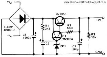
This circuit can be utilized in applications requiring high current and low ripple voltage, such as in high-powered Class AB amplifiers where high-quality audio reproduction is essential. Q1 and Q2, along with resistor R2, function as a power Darlington...
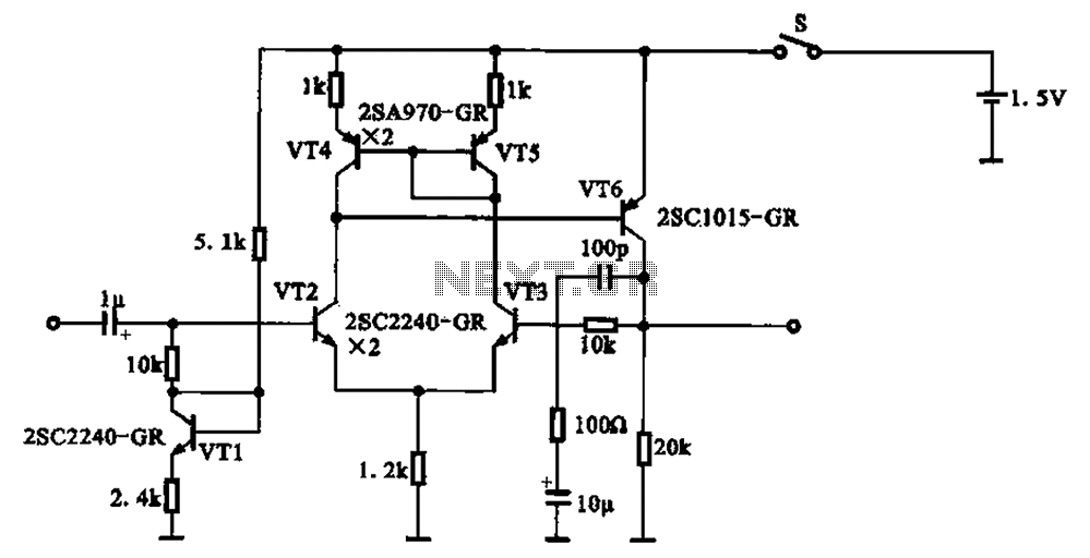
A 1.5V-powered microphone signal amplifying circuit is designed with a power supply for the microphone signal amplification. The circuit primarily consists of a differential amplifier formed by transistors VT2 and VT3. Additionally, VT6 functions as a common emitter voltage...