
Low current consumption lamp flasher
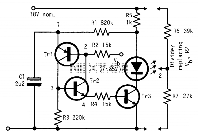
Using the indicated component values, the total period is around 0.55 seconds, with a duty cycle of approximately 7% and a mean battery current, including the Vb divider, of about 1.5 mA.
The circuit described is a simple astable multivibrator configuration that utilizes transistors for generating a square wave output. The choice of transistors is flexible, allowing for various types, which contributes to the circuit's cost-effectiveness. The self-starting nature of the circuit is a significant advantage, ensuring that it begins oscillation without external triggering.
The voltage divider for Vb is critical in determining the base current for Tr3, which affects the oscillation frequency. When Vb is supplied from a fixed voltage source, the circuit's performance becomes sensitive to battery voltage levels, leading to slower flashing as the battery discharges. This behavior should be considered when designing for applications where battery life is a concern.
Resistor R4 plays a vital role in controlling the initial charging current of capacitor C1, which influences the timing characteristics of the circuit. The relationship between R2 and R4, particularly when they are set to equal values, simplifies the design process and allows for predictable timing intervals. The calculation of R2 as R6R7 / (R6 + R7) indicates the importance of selecting appropriate resistor values to achieve the desired timing characteristics.
The timing of the circuit is dictated by the capacitance of C1 and the resistance values of R2 and R1. The on-time and off-time calculations provide a framework for tuning the circuit to achieve specific operational requirements. The resulting period of 0.55 seconds and duty cycle of 7% suggest that this circuit is suitable for low-power applications, where minimal current draw is essential.
Overall, the described circuit is a reliable and efficient solution for generating periodic signals, with flexibility in component selection and straightforward design principles.The circuit is economical in components, and will work with virtually any transistors and is reliably self-starting. The voltage Vb can be taken from a divider, as shown at the right. If taken from a fixed source, flashing becomes slower as battery voltage falls. The lowest drive current into the base of Tr3 is about (Vb—0,6 V)/(R2 + R4). Resistor R4 limits the initial current from Cl and, as shown, R2 and R4 can be roughly equal when a divider is used for Vb.
Resistor R2 equals R6R7/(R6 + R7). With the voltages shown, and with R2 = R4, the on-time is about 1.1 C1R2 and the off-time about 0.28 C1R1. Using the component values shown the period is about 0.55 sec. with a duty cycle of about 7% and a mean battery current including the Vb divider, about 1.5 mA. 🔗 External reference
Related Circuits
This design circuit is for a mass air flow (MAF) sensor. The MAF sensor converts the volume of air entering the engine into a voltage signal. The main components of the MAF sensor include a thermistor, a platinum hot...
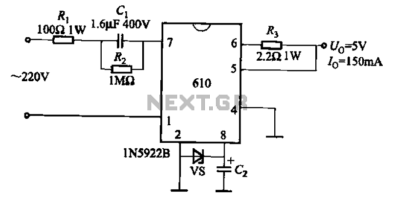
The AX610 Series has a maximum output current of 100 mA and features a scalable output current with an access regulator. The configuration includes two reverse polarity series regulators (2CW106, U: approximately 8.2V) as depicted in Figure (a). Figure...

To create a telephone ring monitor, it is sufficient to connect a resistor in series with a bulb and plug it into a main outlet. The resistance value of this resistor may vary depending on the type of bulb...
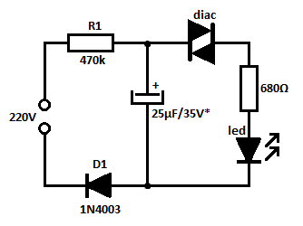
This is likely the simplest concept for generating a flashing light from an LED using alternating current (AC). The circuit provides a straightforward method for flashing one or more LEDs using high-voltage direct current (DC) sourced from mains electricity....
Create LED lighting powered directly from the AC mains (120-Volt AC) due to the unavailability of inexpensive and safe enclosures for the circuitry. While collecting old failed CFLs for recycling, it was noted that the body of CFLs (also...
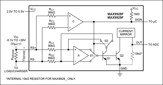
This article compares high-side and low-side amplifiers used for measuring battery charging currents. It recommends selection criteria for current-sense resistors and describes a high-voltage circuit breaker designed for overcurrent protection. High-side and low-side amplifiers are essential components in battery management...