
diac controlled led flasher 3
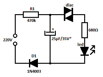
The circuit design described utilizes a straightforward approach to create a flashing LED effect. The key component, the diac, operates as a switch that allows current to flow once the voltage exceeds its threshold, thus controlling the LED's illumination. The inclusion of diode D1 ensures that the alternating current is converted into a usable direct current, which is essential for the operation of the diac and LED. Resistor R1 is critical for limiting the current flowing into the diac, preventing damage and ensuring reliable operation. Resistor R2 serves to further protect the LED by restricting the current to a safe level, preventing potential burnout.
The capacitor C1 plays a vital role in determining the flashing frequency of the LED. By adjusting its capacitance, one can control how quickly the LED turns on and off. This feature allows for customization of the flashing effect, making it suitable for various applications, such as decorative lighting or indicators. The circuit's simplicity makes it an excellent choice for educational purposes, demonstrating fundamental concepts in electronics such as rectification, capacitive charging, and the operation of diacs.
Safety precautions are paramount given the high-voltage nature of the circuit. Proper insulation and housing are necessary to prevent accidental contact with live components. Additionally, the circuit should be tested and operated in a controlled environment to mitigate risks associated with high voltage. Overall, this circuit exemplifies a practical application of basic electronic components to achieve a visually engaging outcome while highlighting essential safety considerations.This is probably the simplest idea to generate flashing light from an LED using AC. The circuit is relatively the simple way of flashing one or more LEDs from a high voltage DC obtained from Mains. This can be used as a Mains indicator or Mock flasher. The circuit uses a diac for the alternate switching of LED. The diac is usually used in pulse ge nerator circuits to trigger SCR and Triac. If a low voltage passes through a diac, it simply behaves like an open circuit and only very low current passes through it. But if the voltage increases to the breakdown threshold of the diac, it will pass heavy current. Usually 35 volt DC is required to attain the threshold level of diac. Unlike SCR, diac conduct in both the directions. In the circuit, a commonly available DB3 diac is used. Diode D1 rectifies AC and generates a high volt DC. Resistor R1 safely controls the DC to operate diac and LED. Normally LED will be OFF. When the capacitor charges fully, diac gets the threshold voltage and fires. This provides current to LED and it lights. Resistor R2 makes the LED current to a safer value of 30 mA. When the diac conducts, C1 discharges and again the breakdown voltage of diac decreases and LED turns off.
Thus the charging/discharging cycles of C1 makes the LED flashing. The value of C1 determines the flash rate. Higher values give slow flash rate and vice versa. If the threshold level of diac is not obtained using the given value of R1, reduce it to 10K, but its wattage should be increased to 5 watts. Caution The circuit is directly connected to high volt AC and there is no galvanic isolation. Take utmost care while handling the circuit. Enclose it in a shock proof case. Do not touch any points when it is connected to Mains. 🔗 External reference
Related Circuits

When the telephone rings or when the handset is lifted, the night light is activated and remains illuminated during the conversation. After the handset is replaced in the cradle, the light stays on for approximately 11 seconds. Under standby...

This is a low-cost circuit diagram for an emergency light utilizing a white LED. Components include an LM317 IC, a resistor, a transformer, an LED, and a variable resistor. The emergency light circuit using a white LED is designed for...
For motorcycle or scooter riders, it is common to forget to deactivate the flashing indicators after making a turn, especially in the absence of an audible reminder. The circuit for an automatic turn signal cancellation system is designed to address...
This circuit functions as a phone message flasher, providing an alternative method to alert users of an incoming call. When the phone rings, a high line voltage is activated. The phone message flasher circuit is designed to enhance the traditional...

The LM3434 adaptive constant on-time DC/DC buck (step-down) constant current controller can be used to design a simple high-power LED driver application. The LM3434 provides a constant current for illuminating high-power LEDs. The output configuration allows the anodes of...

The entire series of TTL monostable multivibrators lacks sufficient speed, prompting the need for an ECL voltage swing that accommodates a wide range of small power requirements. This necessitates the use of F series circuits, which offer fast transition...