
LOW NOISE 420 MHz ATV RECEIVER CONVERTER

The circuit described consists of several key components that work together to process radio frequency signals. L1, Q1, L2, and L3 are integral to the RF amplification stage, where L1 and L2 typically serve as inductors that enhance the gain of the RF signals. Q1, likely a transistor or FET, amplifies the incoming RF signals before they are routed to the mixer.
M1, the doubly balanced mixer, is a critical component for combining the RF signal from Q1 with the local oscillator signal generated by Q4. The operation of the mixer allows for the downconversion of high-frequency signals to a lower intermediate frequency, which is more manageable for further processing. The local oscillator stage, Q4, is tuned to 375 MHz, ensuring that it can effectively mix with the incoming RF signals in the specified 420 to 450 MHz range.
The filtering stage, which includes L6, L7, and C17, is designed to selectively allow only the desired intermediate frequency signals (60 to 70 MHz) to pass through while attenuating unwanted frequencies. This is crucial for maintaining the integrity of the signal and minimizing interference from other frequencies.
The IF amplifier, Q3, boosts the filtered intermediate frequency signal, ensuring that it has sufficient power for subsequent stages in the signal processing chain. The overall performance of this circuit is impressive, achieving a gain of 25 dB and maintaining a low noise figure of less than 2 dB, which is essential for high-quality RF applications.
For those interested in building this circuit, a kit containing all necessary components, including the printed circuit board, is readily available from North Country Radio, providing an accessible option for enthusiasts and professionals alike.L1, Q1, L2, and L3 compose an RF amp’’fter stage that feeds Ml, a doubly balanced mixer. Q4 is alocal oscillator stage In the 375-MHz range Signals h the 420 ‰to 450-MHz range from Q1 are mixed in M1 and fed through filter L6/L7/C17, where only the 60- to 70-MHz (CH3 CH4) signals pass. The IF signal is passed to Q3, an IF amplifier. The overall gatrns 25 dB and the noise figure less than 2 dB. A kit of all parts, including the PC board, is available from North Country Radio, P. O. Box 53, Wykagyl Station, New Rochelle, NY 10804. 🔗 External reference
Related Circuits
This circuit utilizes the versatile MAX038 function generator. While some advanced features of this integrated circuit (IC) are disabled in this configuration, it is capable of generating sine, triangle, and square waves by adjusting the A0 and A1 pins,...
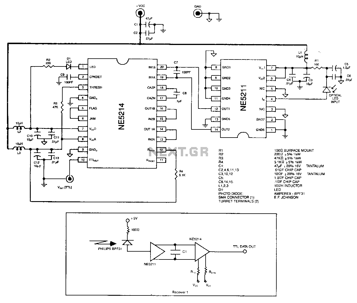
The optical signal is coupled to the pin diode. Current flowing in the diode also flows into the input of the NE5211 preamplifier. The preamplifier is a fixed-gain block that has a 28 kΩ differential transimpedance and performs a...
NJM2268 is a dual video 6dB amplifier designed for S-VHS VCRs, high-bandwidth VCRs, and similar applications. One channel features a clamp function that stabilizes the DC level of the video signal, while the other channel operates as a bias...
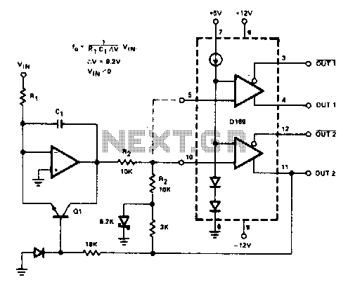
The D169 functions as a level detector, offering complementary outputs. An operational amplifier (op amp) is employed to integrate the input signal Vin, utilizing a time constant defined by the resistor R1 and capacitor C1. A negative input signal...
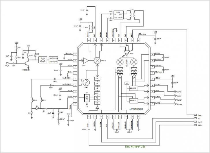
The PB1009K is a silicon monolithic integrated circuit (IC) designed for GPS receivers. This IC incorporates a complete voltage-controlled oscillator (VCO), a second intermediate frequency (IF) filter, a 4-bit analog-to-digital converter (ADC), and a digital control interface, all aimed...
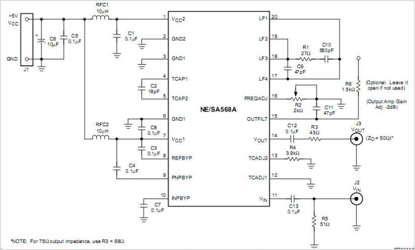
When a DC voltage signal is transmitted over long distances, it experiences attenuation with unpredictable characteristics introduced by the transmission medium, such as cable resistance that varies with temperature changes. In contrast, carrying information using frequency rather than a...