
Low Noise Design Schematics
The circuit design incorporates a distributed active RIAA correction topology, enhancing audio fidelity through precise equalization of frequency response. The use of negative feedback in the input stage serves to linearize amplification, reducing distortion and improving overall sound quality. The Jung regulator's implementation ensures a stable power supply, crucial for minimizing noise interference in sensitive audio applications. The TLE2426 rail splitter efficiently manages the power distribution across the circuit, generating balanced positive and negative rails while maintaining a virtual ground reference.
The choice of components is critical; polypropylene capacitors provide low distortion and high frequency response, while metal film resistors offer superior thermal stability and low noise characteristics. Low-noise operational amplifiers are selected to further enhance the signal integrity, ensuring that the audio path remains clean and free from extraneous noise. The inclusion of relays for muting during power transitions prevents audible thumps, protecting connected speakers from potential damage.
The dynamic range of the circuit is a key specification, indicating its ability to handle a wide range of audio signals without distortion or clipping. The measured equivalent input noise levels are indicative of the circuit's performance, particularly in relation to different cartridge types. The design's adaptability for both MM and MC cartridges highlights its versatility, although it is important to note the limitations in noise performance for low output MC applications.
Overall, the HPS 1.0 and HPS 2.0 designs exemplify a well-thought-out approach to high-fidelity audio preamplification, balancing performance, and practicality while addressing common pitfalls in audio circuit design. The transition from HPS 1.0 to HPS 2.0 illustrates an evolution in design philosophy, focusing on enhanced noise performance and reliability in audio signal processing.I liked the idea of distributed active RIAA correction and also the concept of using negative feedback to linearize the input stage. Now, the original Collin design has a few significant flaws (openly admitted by the author in the same article), one of them being the very poor PSRR in the input stage.
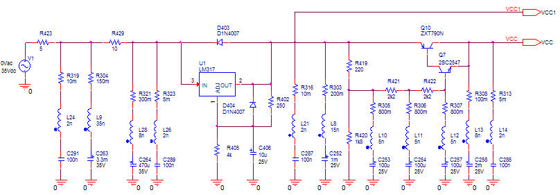
To avoid hum and other noise artifacts to enter the signal chain, this design calls for a solid power supply, much better than the original. So I decided to add a Jung regulator on the same board. The plan was to feed HPS 1. 0 from a 24V wall wart, so some extra circuitry is required to split the power supply. I decided for a TLE2426 rail splitter. This little circuit works great and it`s ideal for balanced rails current; any imbalance flows straight through the virtual ground created by this circuit, so I would advise to be careful in your applications. The HPS 1. 0 currents are already imbalanced by the input stage JFETs, dragging current from the positive supply only.
The TLE2426 gets a little hot, but nothing to worry about. However, further extending the same concept to more paralleled JFETs may create some serious power dissipation issues. There`s not much to tell about construction; just use good quality components (polypropylene caps, metal film resistors) and low noise opamps (AD797 or LT1115, LT1128, LME49710, OPA211 on a SMD adaptor) and the good results are guaranteed.
The relays are DIP case 12V models. It is a good idea to mute the preamps before powering up/down or switching the gain to avoid a large thump into the speakers. For this build, the dynamic range (aka the headroom) is around 22dB at 1KHz, for the max gain of 64dB and +/-17V supplies.
This is not bad, but has a certain audible as you`ll find later on this page. As you will find in the Measurement sections, the equivalent input noise of this construction is about 0. 9nV/rtHz. This is very good for a MM cartridge (the NAD PP3 preamp has 8nV/rtHz for the MM input) but not that great for MC.
The hiss is clearly audible, on the 64dB gain setting, even in not very sensitive speakers. Therefore, even if it has the required gain, I cannot recommend this construction for low output MC cartridges; you may want to look at the HPS 2. 0 below for that. Although the Jung regulator helps in reducing the hum and noise artifacts injection in the input stage, some residuals (captured from the supply input wiring and the ambient, the case is aluminum) are still slightly audible; again, refer to HPS 2.
0 for a low output MC cartridge. - HPS 2. 0 uses 4 2SK170 low noise JFETs in the input stage. The equivalent input noise of the input stage is inversely proportional to the square of the number of paralleled input devices; it is therefore expected, theoretically, HPS 2. 0 to have half the noise of a single 2SK170 input stage (1-1. 2nV/rtHz) plus the contribution of the source resistor (10ohm, 0. 4nV/rtHz). - A dedicated power supply (to replace the wall wart and the TLE2426 rail splitter) was added as well.
To keep hum to a minimum, this supply was designed as a separate unit. Both PCBs will fit each in the same extruded aluminum case as for HPS 1. 0. Two 5 pin connectors and an appropiate cable are required to connect the power supply to the preamp. The same construction details as for HPS 1. 0 apply. HPS 2. 0 has the same gain, the same dynamic range as HPS 1. 0 but a much improved noise performance. As you will find in the Measurements secton, the equivalent input noise is around 0. 6-0. 7nV/rtHz; it can be therefore successfully used with MC cartridges down to 0. 5-0. 7mV output at 5cm/sec. The only criticism I was able to hear about HPS 1. 0 and 2. 0 (beyond the regular grumble 🔗 External reference
Related Circuits
The aquarium design utilizes a DPDT relay and a 12V inverter. The selected relay is rated adequately for a 400-watt load. The 12V DC relay, transformer, and diodes consume minimal power, making efficiency a minor concern. It is unclear...
The problem with class-B amplifier design is that we start with an output stage in two halves, each with a non-linear response, which we then add together to try to give a linear response, i.e. so that a graph...
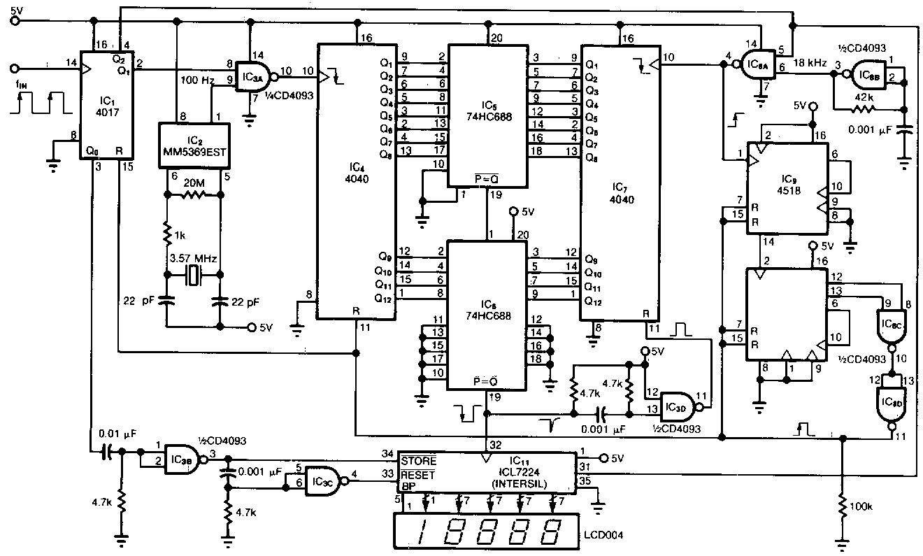
This tachometer measures heartbeats, respiratory rates, and other low-frequency events occurring at intervals ranging from 0.33 to 40.96 seconds. The circuit detects the period of the event, calculates the corresponding pulses per minute, and updates the LCD display accordingly....
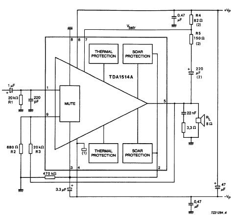
The TDA1514 audio amplifier circuit design is an electronic project capable of delivering high audio power output using a specialized audio integrated circuit (IC) and a few common components. Manufactured by Philips Semiconductor, the TDA1514 audio IC can provide...
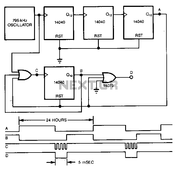
A precise pulse generator can be constructed using a precision oscillator and several CMOS counters. The number of counters can be increased to extend the pulse period as needed. This circuit will generate a pulse approximately 5 ms long...

This second-order low-pass filter utilizes a 741 operational amplifier and can be tuned from 2.5 kHz to 25 kHz. The circuit is beneficial in audio and tone control applications. R1 and R2 are ganged potentiometers. The described circuit features a...