
Variable Low-Pass Filter Circuit

The described circuit features a second-order low-pass filter configuration, which is designed to allow signals with a frequency lower than a specified cutoff frequency to pass through while attenuating frequencies higher than this threshold. The use of a 741 operational amplifier provides the necessary gain and buffering for the input signal, ensuring that the filter maintains signal integrity and performance.
The tuning capability of the filter, ranging from 2.5 kHz to 25 kHz, is achieved through the integration of ganged potentiometers, R1 and R2. These potentiometers allow simultaneous adjustment of resistance values, effectively altering the cutoff frequency of the filter. This tunability is particularly advantageous in audio applications where precise control over frequency response is required for tone shaping and signal processing.
In the schematic, the operational amplifier is configured in a feedback loop that includes capacitors and resistors arranged to define the filter characteristics. The capacitors determine the frequency response, while the resistors set the gain and the damping factor of the filter. The ganged potentiometers enable the user to modify both the resistance and the capacitance, allowing for fine-tuning of the filter's performance to suit specific audio needs.
Overall, this low-pass filter circuit is a versatile tool for audio engineers and hobbyists alike, providing a practical solution for managing audio frequencies in various applications, such as equalization, crossover networks, and other tone control systems. This second-order low-pass filter uses a 741 op amp and is tuneable from 2.5 kHz to 25 kHz. This circuit is useful in audio and tone control applications. R1 and 2 are ganged potentiometers. 🔗 External reference
Related Circuits
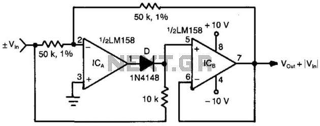
When the input voltage is positive, the output of ICA is negative, resulting in diode D not conducting; therefore, the output of ICB is positive. Conversely, when the input is negative, the output of ICA becomes positive. Diode D...
Often, for various reasons, individuals forget or are unable to water the plants in their homes. Many humidity sensor units merely alert users with a beeping sound or a flashing light when the pot requires watering. However, what if...
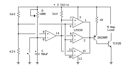
In this circuit, an LM339 quad voltage comparator is used to generate a time delay and control a high current output at low voltage. Approximately 5 amps of current can be obtained using a couple of fresh alkaline D...
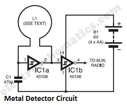
The metal detector circuit presented here exemplifies simplicity while demonstrating effective functionality. It utilizes a single 40106 hex Schmitt inverter IC, a capacitor, a search coil, and batteries. A connection from IC1b pin 4 must be made to a...
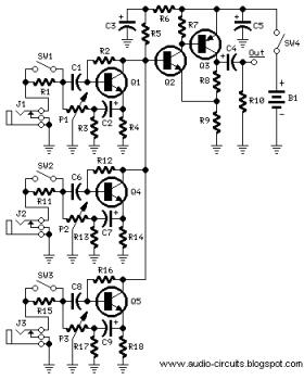
The following circuit illustrates a Mini Audio Mixer with Level Control Circuits. Features include switchable high/low sensitivity, providing high performance. The Mini Audio Mixer circuit is designed to facilitate the mixing of multiple audio signals while allowing for level control...
A series of emails have been received requesting schematics for infrared remotes. This document presents a schematic for such a remote, which transmits a tone using an infrared LED. The tone is decoded by the receiver, ensuring that the...