
LOW POWER FM TRANSMITTER
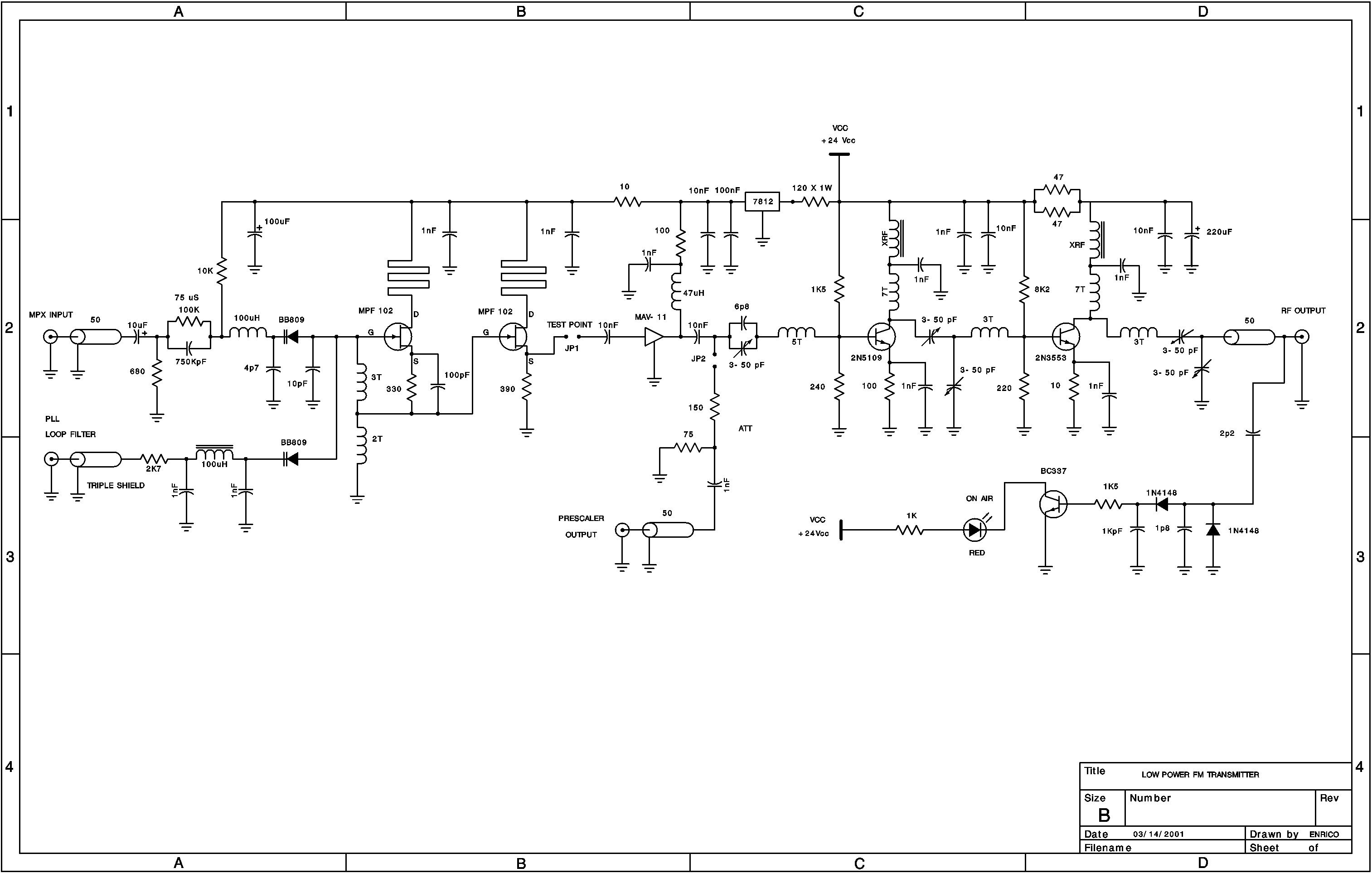
5 dBm, at my project I used a MWA-130 ( from Motorola) as driver stage. At second stage I used a 2N5109 (Motorola), but you can also use a 2N3866, and at final stage a 2N3553. With proper biasing and setting up the trimmers to maximum output power you can achieve around 2. 8 watts of EIRP using a 0 dBi antenna. A good irradiant system is also important, as well the coax cable that I recommend low loss cables if you are using a long cable distances.
RG-58A haves a 67% of propagation velocity and 21. 65 dB/100m of insertion loss at 146 MHz. I also recommend you use a low pass filter at final stage to prevent harmonics products cause harmful interferences on the MARS/CAP systems. Here in Brazil, many pirate radios don`t use such filter causing many trouble at MARS service. At final you can found many schematics, and of couse a suggested low pass chebyshev filter and the respective response frequency curve.
You will experience a low insertion loss within this filter, but not so expressive. The VCO can operate as free ( open loop) or synthesized (PLL) oscillator, you just must insert a jumper to close the loop for PLL or release it to free oscillator operation. The frequency deviation is controled by varactor diode that change the instrinsic capacitance within the voltage audio input causing a frequency deviation.
Note: set it to ± 75 KHz to FM pattern broadcast operation. Another varactor BB809 control the operation frequency, 200 KHz step increments is allowed at PLL schematic circuit at final of this page, the oscillator was constructed to operate in FM broadcast (88 to 108 MHZ) without any change in components. As hartley oscillator, if you wanna change the operation frequency just change the numbers of turns in the inductors at LC tank circuit.
As you know, decreasing the numbers of turns, you get upper frequencies, and vice-versa. Pay attention to start up the oscillator if you wanna change it to operate in high frequency than FM braodcast. Following the Barkhausen Criteria, we have a feedback in a simple amplifier and also sustain the oscillations, so the K fator( Loop gain) must be equal to one.
The MPF 102 oscillator transistor operates quite good until 150 MHz, a high Ft transistor will be required to high frequency operation. If you could use a network of varactors diode ( paralel association) to control the frequency deviation would be interesting because the BB809 have hyper abrupt curves.
Maybe MV209 in paralel produces less distortion and also ensure more linearity. At input ( audio signal), I did a pre-emphasis network to garantee that modulation index at high audio frequencies ( up 1KHz). At FM radio, the relation S/N depends of modulation index employed. The index decrease as modulation frequency increases, to a constant frequency deviation. Pre-emphasis is a high pass filter, that the cutoff frequency is slight upper of a maximum modulated frequency.
The filter must provide 6dB/octave, that can be stablished by a series capacitor with the patch audio signal. Between the oscillator and driver, a buffer stage was inserted to prevent oscillations and increase isolation, high impedance at gate ( oscillator side) and low impedance at source terminal.
At MAV-11 output there are a sample frequency output to the pre-scaler ( if using PLL), and under the conditions of a high power, I added a resistive PI attenuator of 8 dB, it prevents not overload the pre-scaler input. The driver stage is the own MAV-11 with 12 dB of gain, I choose the 🔗 External reference
Related Circuits
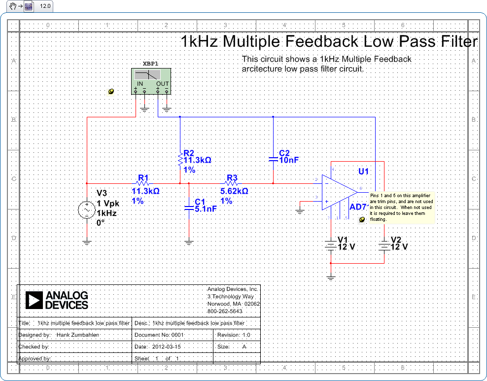
Pins 1 and 5 on this amplifier are trim pins and are not utilized in the circuit. When not in use, it is necessary to leave them floating. In electronic amplifier circuits, trim pins are often included for calibration or...

This is an adjustable and regulated power supply with an output voltage range of 3V to 30V and a current supply capability of up to 3A. This circuit is equipped with short circuit protection and overload protection. The adjustable power...
The schematic diagram originates from a circuit designed as a battery charger/power supply with an output of 14V and a maximum current of 4A, utilizing the VN64GA MOSFET. This high-performance battery charger is specifically engineered for gelled electrolyte lead-acid...
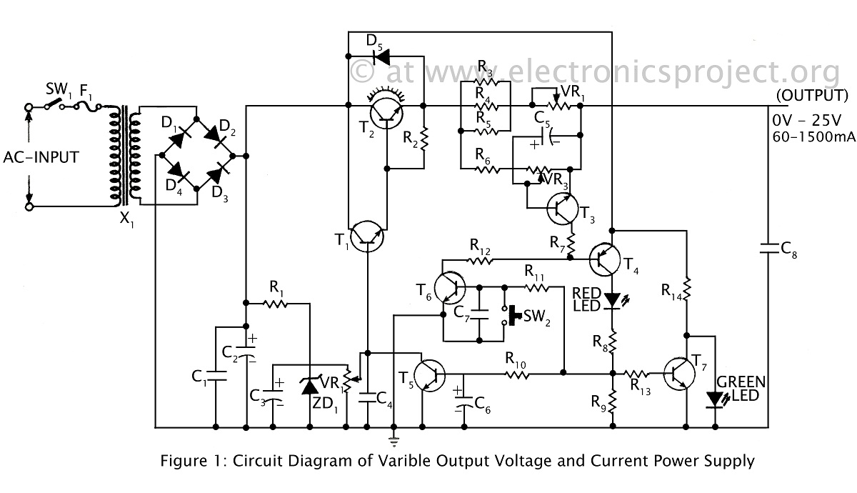
A ripple-free, short-circuit protected variable output voltage and current power supply is presented on this website as a verified project. The circuit diagram includes a description of various power supply circuits. This power supply circuit is designed to provide a...
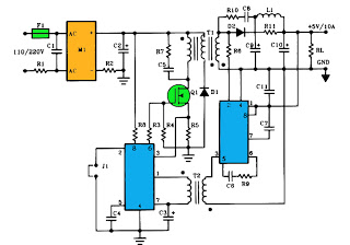
The schematic above illustrates a 10A power supply with a 5V output and a power rating of 50W. It operates as a flyback converter in continuous mode. The circuit includes both primary and secondary side controllers, providing comprehensive protection...
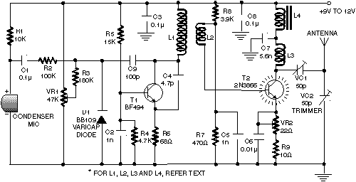
A highly effective 1-watt FM transmitter circuit that is easy to construct. The circuit consists of four transistors: one functions as a stable oscillator, followed by a buffer stage to maintain frequency stability during adjustments. Next is a resonance...