
1khz multiple feedback low pass filter circuit

In electronic amplifier circuits, trim pins are often included for calibration or adjustment purposes, but they may not always be necessary for the amplifier's operation. In this case, pins 1 and 5 are designated as trim pins, indicating that they serve no function in the current configuration of the circuit. It is essential to ensure that these pins remain unconnected or "floating" to prevent any unintended effects on the amplifier's performance.
Floating these pins means that they should not be connected to ground or any voltage source, as this can introduce noise or instability in the amplifier's operation. Proper handling of unused pins is crucial in maintaining the integrity of the circuit and ensuring optimal performance.
When designing or implementing this amplifier circuit, attention must be paid to the layout and connections to avoid accidentally connecting these trim pins to other circuit elements. Careful documentation and adherence to the schematic will facilitate correct assembly and operation of the amplifier, ensuring that it functions as intended without interference from unused components.Pins 1 and 5 on this amplifier are trim pins and are not used in the circuit. When not used it is required to leave them floating. 🔗 External reference
Related Circuits
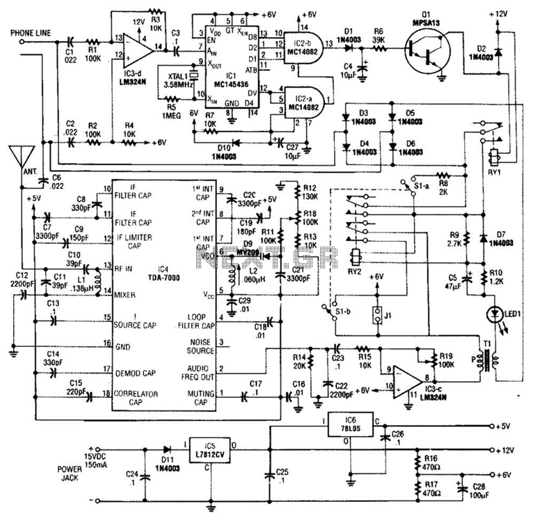
When the asterisk (*) is pressed on the touch-tone phone, a DTMF decoder, referred to as TCI, manages the on-hold logic. Audio from the FM receiver IC4 is transmitted over the telephone line when a hold condition is active....
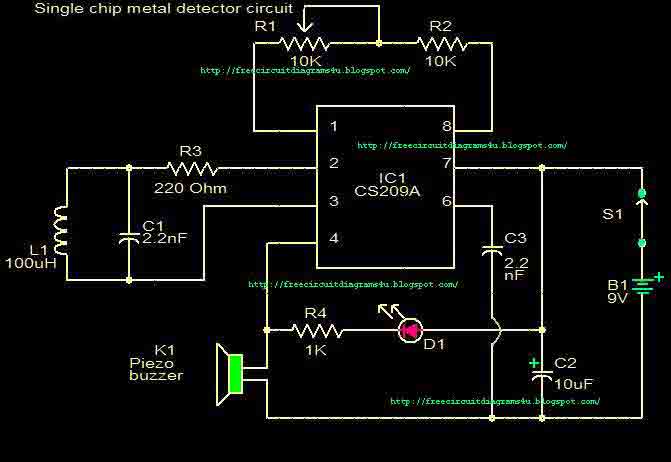
This circuit is a single chip metal detector. Actually, we can use this one to detect metals. Especially, you have seen some army soldiers keep something to detect metals. That equipment has been made through this circuit. So you...

The core multi-resonant circuit 40 L06 has a collapse time of 1C. An auxiliary electric signal operates below its low threshold, opening Icl. The output is provided through two terminals for business use. The circuit includes components such as...
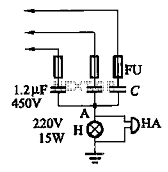
A 3-phase power system poses risks to electrical equipment, particularly asynchronous motors. To detect phase failure, an alarm circuit can be implemented. When the power supply is normal, the voltage at point A is approximately 0V, and no alarm...
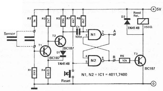
This humidity detector circuit diagram is straightforward and utilizes a limited number of components. It can be employed to activate electronic devices when the detector identifies a specific humidity level. The sensor is made from two copper pieces positioned...
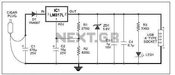
This USB car charger circuit adapter is designed for use with a car's cigarette lighter socket. It functions as a DC-DC power converter, effectively converting the 12V voltage from the car battery into a stable 5V output. This circuit...