
Low Power Voltage Doubler

In this circuit, IC1 is configured as an astable multivibrator generating rectangular pulses at approximately 10 kHz. The frequency and duty cycle of these pulses can be adjusted using preset VR1. The generated pulses drive switching transistors T1 and T2, which are arranged to form the voltage-doubling section. The doubled voltage is available across capacitor C5. During each pulse cycle, the high level activates T1, keeping T2 off. This allows T1 to charge capacitor C4 through diodes D1 and D2 to a voltage slightly less than the supply voltage. During the low period of the pulse, T1 turns off while T2 is activated, raising the charge on the negative terminal of capacitor C4 by an amount equal to the supply voltage. Consequently, an equivalent charge builds up on capacitor C5 via diode D3. This doubling mechanism results in a total voltage across capacitor C5 that is nearly double the input voltage.
If the pulse generator output is maintained at a sufficient amplitude and frequency, the output voltage and current will remain stable to meet the load requirements. The circuit exhibits minimal ripple voltage, even with a half-wave function. If the load does not demand high current, efficiency can reach the upper 90 percent range. It is important to note that while the input voltage is doubled, the current drawn from the input power supply also doubles, resulting in a halved output current. Caution should be taken when operating the multivibrator at higher frequencies, as this may introduce interference to the DC output voltage. The frequency should be optimized through trial and actual load connection procedures. This compact circuit can be built on a general-purpose PCB, and if all components are surface-mount types, the entire module can be significantly miniaturized.All miniature electronic devices operate off batteries. Some of them need higher than the standard battery voltages to operate efficiently. If the battery of that specific voltage is unavailable, we are forced to connect additional cells in series to step up the DC voltage. Thus, the true meaning of miniaturisation is lost. A simple way to overcom e this problem is to employ a voltage doubler, if the device under consideration can operate at a small current. Here we present a low-power voltage doubler circuit that can be readily used with devices that demand higher voltage than that of a standard battery but low operating current to work with.
The circuit is quite simple as it uses only a few components. Yet, the output efficiency is 75 to 85 percent along its operating voltage range. The available battery voltage is almost doubled at the output of the circuit. Here IC1 is wired as an astable multivibrator to generate rectangular pulses at around 10 kHz. This frequency and duty cycle of the pulses can be varied using preset VR1. The pulses are applied to switching transistors T1 and T2 for driving the output section, which is configured as a voltage-doubling circuit. The doubled voltage is available across capacitor C5. During each cycle of the pulse occurance, the high level drives T1 into its saturation, keeping transistor T2 cut off.
So transistor T1 charges capacitor C4 via the path formed by diodes D2 and D1 to a voltage level slightly lesser than the supply. But during the low period of the pulse, transistor T1 is cut off while transistor T2 is driven into saturation.
Now, transistor T2 raises the charge on the negative pole of capacitor C4 by another step equal to the supply voltage. Therefore an equal amount of charging is built up on capacitor C5 via diode D3. This doubling action increases the total voltage across capacitor C5 to almost double the input voltage.
If the output of the pulse generator is maintained with a high enough amplitude and frequency, the output voltage and current remain constant and cater to the needs of the load. Even with the half-wave function, this circuit is almost free of ripple voltage. If the connected load doesn`t require a high current, the efficiency can be expected in the upper 90 percentranges.
Since the input voltage is doubled, the current drain from the input power supply is also doubled at the input but halved at the output. One point of caution is that if the multivibrator`s frequency is fairly high, the output may suffer with the interference imposed over the DC voltage.
In this case, the frequency must be set favorably by trials and actual load connection procedure. This tiny circuit can be assembled on the general-purpose PCB. If all of the components are surface-mount type, the whole module can be genuinely miniaturized. 🔗 External reference
Related Circuits
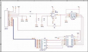
This example demonstrates the design of a circuit that incorporates both analog and digital components, features multiple power planes, and utilizes a single ground plane that is divided into analog and digital sections while maintaining a common reference point. The...
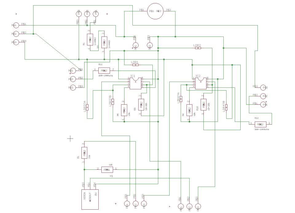
One of the motors consistently exhibits hesitation and operates in an unpredictable manner. When tested independently, the motors function correctly without any hesitation. The GPS unit features a Low Voltage TTL serial output on its connector, but a reliable...
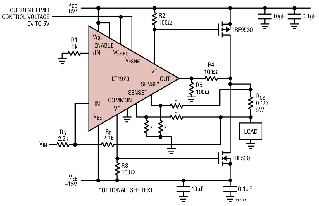
This week, a new favorite chip, the LT1970 power operational amplifier from Linear Technology, is introduced. This device operates from a 36 V supply and can source or sink 500 mA. It features programmable current limiting, outputs for indicating...
A compact power amplifier that delivers high-quality sound. It incorporates a NE5534 operational amplifier, known for its excellent performance, capable of handling low loads, providing high speed, and exhibiting low distortion. Additionally, it features two V-MOSFET transistors at the...
The FAN4810 operates as a continuous conduction mode (CCM) power factor correction (PFC) controller. It features an internal safety detection mechanism that prevents circuit malfunction due to component damage. The device has a power-handling capability of up to 1A,...
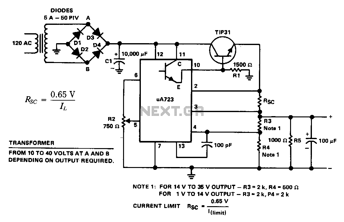
The supply 6-66 can be utilized for output voltages ranging from 1 to 35 V. The line transformer must be selected to provide approximately 1.4 times the desired output voltage from the positive side of filter capacitor C1 to...