
Low Tech FM Radios
The FM radio technology is based on the principle of frequency modulation, where the information is encoded in the frequency variations of the carrier wave. The superheterodyne architecture is a common approach used in FM receivers, where the incoming RF signal is mixed with a locally generated signal to produce an intermediate frequency (IF) that is easier to process. The wideband IF stage allows for the reception of a broad spectrum of frequencies, enhancing the receiver's ability to capture signals with varying modulation depths.
The limiter stage is crucial for maintaining signal integrity by removing amplitude variations caused by noise, ensuring that only the frequency information is passed to the discriminator. The discriminator then converts the frequency deviations back into audio signals, allowing for clear sound reproduction.
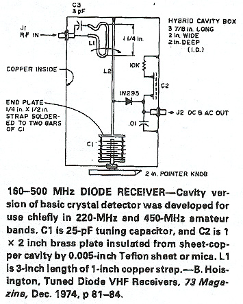
In constructing a simple FM radio crystal set, a tuned circuit is essential for selecting the desired frequency. The circuit typically consists of an inductor and capacitor configured to resonate at the frequency of the incoming FM signal. The crystal diode acts as a detector, converting the amplitude variations induced by the tuned circuit into an audio signal.
Slope detection, while not providing the full benefits of FM, allows for a low-cost solution to receive FM signals using AM equipment. The tuning process requires careful adjustment to achieve optimal reception, particularly by offsetting the FM signal from the center frequency of the receiver.
In more advanced applications, regenerative amplifiers can be employed to enhance the sensitivity of the receiver. By incorporating feedback mechanisms, these amplifiers can achieve high gain levels, improving the overall performance of the FM receiver. The design of such circuits requires careful consideration to prevent unwanted oscillations while maximizing gain and maintaining stability.
Overall, FM radio technology represents a significant advancement in broadcast communication, providing clearer audio quality and greater resistance to interference compared to its AM counterparts. The evolution of FM receiver designs continues to reflect the balance between complexity and performance, catering to various applications in the field of electronics.Broadcast band frequency modulation (FM) radio was invented to solve existing problems with noise and fidelity on the amplitude modulation (AM) broadcast band. Thus, the first FM receivers were quite complex in design, employing a superheterodyne converter, a wideband IF, a limiter stage, and a discriminator.
Unlike the first AM radio sets, the ea rliest FM radio sets did not use the simplest possible methods for receiving signals. Perhaps Armstrong, the inventor of most modern radio methods, was fully aware of all the ways to receive FM. (Someone reading these comments might want to offer the technical history so I can add it here. ) But, it was not until much after the introduction of commercial broadcast FM that simple FM receiver designs were published or sold.
Although the title alludes to simplicity, these radio designs are not uniformly simple. These designs generally have low component counts, however the design or construction my have been far from simple. Believe it or not, you can actually make an FM radio crystal set. The key to understanding how this simple circuit can decode FM is to understand what happens when an FM signal is coupled to a tuned circuit.
A good tuned circuit (one with a high "Q factor") will attenuate signals that are not near its resonant frequency. If you apply a FM signal to a good tuned circuit, as the frequency of the FM signal moves away from the resonant frequency of the tuned circuit, the tuned circuit will attenuate that signal.
As the frequency of the FM signal moves toward the resonant frequency of the tuned circuit, the tuned circuit will let more of the signal pass through. Thus, a tuned circuit will impose amplitude changes on a FM radio signal that match the frequency changes.
A crystal diode is sensitive to amplitude changes, so it converts the amplitude changes into a signal that the listener can hear through headphones. Using a tuned circuit to induce amplitude changes onto an FM signal, then converting the amplitude changes to sound frequencies, is called slope detection.
"Slope" refers to the slope of the tuned circuits` attenuation curve. If you have an AM receiver, you can listen to a FM signal by using the slope of the tuned circuits in the receiver. This method gives you none of the real advantages of FM. For instance, FM is noted for its immunity to static. An AM receiver used to slope detect will hear static. The only real advantage to slope detection is that is can be cheap and convenient. When tuning in an FM signal with an AM receiver, the clearest sound occurs when the FM center frequency is offset from the center frequency of the receiver`s tuned circuits.
If the FM signal is at the receiver`s center frequency, then frequency deviations both up and down produce downward amplitude changes. When the FM signal is off center, up and down frequency changes create up an down amplitude changes in the receiver.
Believe it or not, an oscillator is an FM detector. If an FM signal is coupled into the tuned circuit of an oscillator, there will be an additive effect between the FM signal and the oscillator`s signal when the two match exactly in frequency. This additive effect will show up as slightly stronger oscillator signal amplitude. As the FM signal swings away from this perfectly matching frequency, the additive effect will diminish.
Just like with slope detection, the amplitude variations can be used to create an audible signal. The non-linearity of most oscillators will detect the amplitude variations without the need for a diode detector. One way to maximize the gain of an amplifier is to design a circuit that lets the operator control the gain.
With sufficient positive feedback, a circuit can be designed that has lots of gain, but will oscillate if its gain is set too high. This type of circuit is called a regenerative amplifier. If a regenerative amplifier includes a high Q tuned circuit, then that amplif 🔗 External reference
Related Circuits
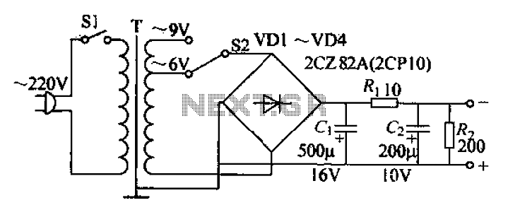
The adjustable current power supply circuit operates at 6V and 9V, utilizing a minimal number of components, which facilitates easy assembly. The circuit can deliver an adjustable output current of up to 100mA, serving as a suitable alternative to...

This is a simple and low-cost NiCd and NiMH battery charger. The schematic diagram indicates that the charging current (I) should be set to 1/10 of the battery's rated capacity. For instance, if the battery has a rated capacity...

In electronic technology, the triode utilizes a variety of general components and parts. The parameters of the triode and numerous electrical parametric measurement schemes are closely related to measurement results. Therefore, in electronic design, the base pin, typological judgment,...

The fan operates continuously in many PCs, which may not be necessary. A simple controller circuit can adjust the fan speed based on demand. This not only conserves energy but also minimizes noise irritation from the fan. Only three...

Many later radios utilize four 7-pin valves and require a high tension (HT) supply of 90V at approximately 12mA, and a low tension (LT) supply of either 125mA or 250mA, depending on the specific valves used. The original batteries...

The figures above illustrate the fundamental concept of a robot, which comprises input and output devices connected to a central processing unit, often referred to as the brain. In this case, the Arduino acts as the brain, controlling all...
Warning: include(partials/cookie-banner.php): Failed to open stream: Permission denied in /var/www/html/nextgr/view-circuit.php on line 713
Warning: include(): Failed opening 'partials/cookie-banner.php' for inclusion (include_path='.:/usr/share/php') in /var/www/html/nextgr/view-circuit.php on line 713